Nissan Versa (N17): Front drive shaft
Exploded View
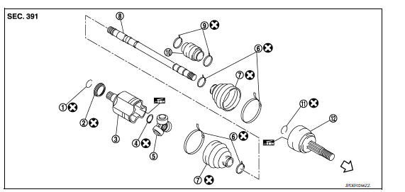
1. Circlip 2. Dust shield 3. Slide joint housing
4. Snap ring 5. Spider assembly 6. Boot band
7. Boot 8. Shaft 9. Damper band
10. Dynamic damper 11. Circlip 12. Joint sub-assembly
 Wheel side
Disassembly and Assembly
DISASSEMBLY
Transaxle Side
- Fix shaft with a vise.
CAUTION: Protect shaft using aluminum or copper plates when fixing with a vise.
- Remove boot bands, and then remove boot from housing.
- Put matching marks on housing and shaft, and then pull out housing from
shaft.
CAUTION: Use paint for matching marks.
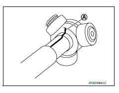
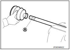
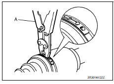
- Put matching marks (A) on the spider assembly and shaft.
CAUTION: Use paint for matching marks.
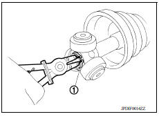
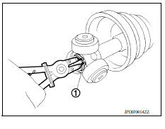
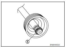
- Remove snap ring (1), and then remove spider assembly from shaft.
- Remove boot from shaft.
- Remove dust shield from housing.
- Remove circlip from housing.
- Remove damper bands, then remove dynamic damper from shaft.
Wheel Side
- Secure shaft in a vise.
CAUTION: Protect shaft when securing it in a vise using aluminum or copper plates.
- Remove boot bands, then remove boot from joint sub-assembly.
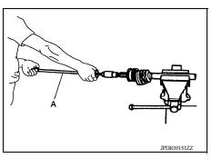
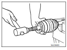
- Screw a suitable tool (A) into joint sub-assembly screw part to a length of 30 mm (1.18 in) or more. Support drive shaft with one hand and pull out joint sub-assembly from shaft.
CAUTION:
- Align drive shaft puller and drive shaft, remove by pulling firmly and uniformly.
- If joint sub-assembly cannot be removed after five or more unsuccessful attempts, replace shaft and joint subassembly as a set.
- Remove circlip from shaft.
- Remove boot from shaft.
INSPECTION AFTER DISASSEMBLY
Check the following items, and replace the part if necessary.
Shaft
Check shaft for runout, cracks, or other damage.
Dynamic Damper
Check damper for cracks or wear.
Joint Sub-Assembly (Wheel Side)
Check the following:
- Joint sub-assembly for rough rotation and excessive axial looseness.
- The inside of the joint sub-assembly for entry of foreign material.
- Joint sub-assembly for compression scars, cracks, and fractures inside
of joint sub-assembly.
Replace joint sub-assembly if there are any non-standard conditions of components.
Housing and spider assembly (Transaxle Side)
Replace housing and spider assembly if there is scratching or wear of housing roller contact surface or spider roller contact surface.
NOTE: Housing and spider assembly are used in a set.
ASSEMBLY
Transaxle Side
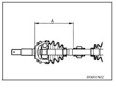
- Install dynamic damper, follow the procedure described below.
a. Install dynamic damper to shaft.
b. Secure dynamic damper with bands in the specified position.
CAUTION: Do not reuse bands.
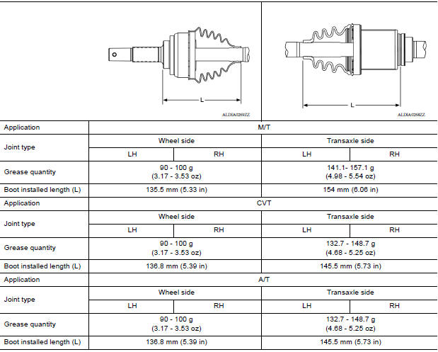
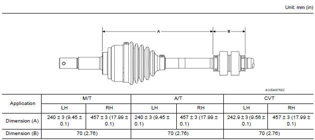
Dimension (A) : Refer to FAX "Drive Shaft".
- Remove any old grease that exists on the housing.
- Install dust shield.
CAUTION: Do not reuse dust shield.
- Install circlip to housing.
CAUTION: Do not reuse circlip.
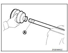
- Install new boot and boot bands to shaft.
CAUTION:
- Wrap serration on shaft with tape (A) to protect boot from damage.
- Do not reuse boot and boot bands.
- Remove the tape wrapped around the serration on shaft.
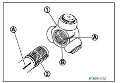
- To install the spider assembly (1), align it with the matching marks (A) on the shaft (2) during the removal, and direct the serration mounting surface (B) to the shaft.
- Secure spider assembly onto shaft with snap ring (1).
CAUTION: Do not reuse snap ring.
- Apply the appropriate amount of grease to spider assembly and sliding surface.
- Assemble the housing onto spider assembly, and apply the balance of the specified amount grease.
Grease quantity : Refer to FAX "Drive Shaft".
- Align matching marks put during the removal of housing.
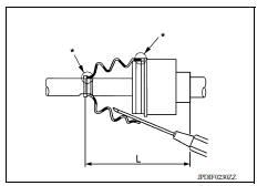
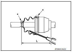
- Install boot securely into grooves (indicated by "*" marks).
CAUTION: If grease adheres to the boot mounting surface (with "*" mark) on shaft or housing, boot may be removed. Remove all grease from the surface.
- To prevent the deformation of the boot, adjust the boot installation length to the value shown below by inserting the suitable tool into the inside of boot from the large diameter side of boot and discharging inside air.
Boot installation length (L) : Refer to FAX"Drive Shaft".
CAUTION:
- If the boot installation length exceeds the standard, it may cause breakage of the boot.
- Be careful not to touch the inside of the boot with the tip of tool.
14. Install large and smaller boot bands securely.
CAUTION: Do not reuse boot bands.
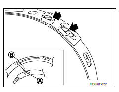
a. Put boot band in the groove on drive shaft boot. Then fit pawls into holes to temporary installation.
 : Pawl
NOTE:
For the large diameter side, fit projection (A) and guide slit (B) at
first.
: Pawl
NOTE:
For the large diameter side, fit projection (A) and guide slit (B) at
first.
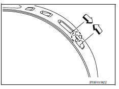
b. Pinch projection on the band with suitable pliers to tighten band.
c. Insert the tip of band into the lower part of pawl as shown.
 : Pawl
15. Check that displacement does not occur when boot is rotated with the housing assembly fixed.
CAUTION:
- If displacement occurs, replace band.
- Do not reuse boot band.
Wheel Side
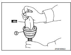
- Clean the old grease on joint sub-assembly with paper waste.
- Fill serration slot joint sub-assembly (1) with NISSAN genuine
grease or equivalent until the serration slot and ball groove
become full to the brim.
CAUTION: After applying grease, use a paper waste to wipe off old grease that has oozed out.
- Install boot and boot bands to shaft.
CAUTION:
- Wrap serration on shaft with tape (A) to protect the boot from damage.
- Do not reuse boot and boot band.
- Remove the tape wrapped around the serration on shaft.
- Position the circlip (1) on groove at the shaft edge.
CAUTION: Do not reuse circlip.
NOTE: Drive joint inserter is recommended when installing circular clip.
- Align both center axles of the shaft edge and joint sub-assembly.
Then assemble shaft with joint sub-assembly holding circular clip.
- Install joint sub-assembly to shaft using plastic hammer.
CAUTION:
- Check circlip is properly positioned on groove of the joint sub-assembly.
- Confirm that joint sub-assembly is correctly engaged while rotating drive shaft.
- Apply the specified amount of grease into the boot inside from large diameter side of boot.
Grease quantity : Refer to FAX "Drive Shaft".
- Install the boot securely into grooves (indicated by "*" marks).
CAUTION: If grease adheres to the boot mounting surface (indicated by "*" mark) on the shaft or joint subassembly, boot may be removed. Remove all grease from the boot mounting surface.
- To prevent the deformation of the boot, adjust the boot installation length to the specified value shown below by inserting the suitable tool into inside of the boot from the large diameter side of the boot and discharging the inside air.
Boot installation length (L) : Refer to FAX "Drive Shaft".
CAUTION:
- If the boot installation length exceeds the standard, it may cause breakage of the boot.
- Be careful not to touch the inside of the boot with a tip of tool.
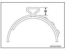
11. Secure the large and small ends of the boot with boot bands using Tool (A).
Tool number : KV40107300 ( - )
CAUTION:
- Do not reuse boot band.
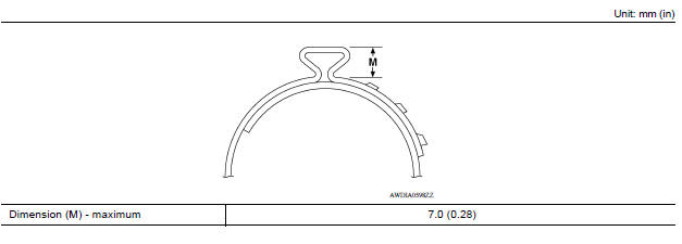
- Secure boot band so that dimension (M) meets the specification as shown.
Dimension (M) : Refer to FAX "Boot Bands".
12. Check that displacement does not occur when boot is rotated with the joint sub-assembly and shaft. CAUTION: Do not reuse boot band.
SERVICE DATA AND SPECIFICATIONS (SDS)
Wheel Bearing
Drive Shaft
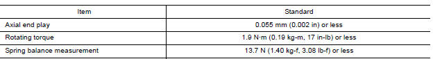
Dynamic Damper
Boot Bands
 Front drive shaft
Exploded View 1. Drive shaft 2. Cotter pin A. Apply Molykote M77 Removal and Installation REMOVAL Remove the wheel and tire assembly using power tool. Refer to WT "Adjustment" ...

Other materials:
Exhaust valve timing control
Exhaust valve timing control : system diagram
Exhaust valve timing control : system description
INPUT/OUTPUT SIGNAL CHART
Sensor
Input signal to ECM
ECM function
Actuator
Crankshaft position sensor (POS)
Engine speed*1
Piston position
Exhaust valve timing c ...
EVAP canister vent control valve
Exploded View
1. EVAP canister 2. O-ring 3. EVAP canister vent control valve
4. EVAP canister vent control valve hose
Removal and Installation
NOTE:
The EVAP canister vent control valve can be removed without removing the EVAP
canister.
REMOVAL
Remove the EVAP canister protector cov ...
Categories
- Manuals Home
- Nissan Versa Owners Manual
- Nissan Versa Service Manual
- Video Guides
- Questions & Answers
- External Resources
- Latest Updates
- Most Popular
- Sitemap
- Search the site
- Privacy Policy
- Contact Us

0.0057