Nissan Versa (N17): P2096, P2097 A/F sensor 1
DTC Logic
DTC DETECTION LOGIC
| DTC No. | Trouble diagnosis (Trouble diagnosis content) | DTC detecting condition | Possible cause |
| P2096 | POST CAT FUEL TRIM SYS B1 (Post catalyst fuel trim systemtoo lean bank 1) | The output voltage computed by ECM from the A/F sensor 1 signa is shifts to the lean side for a specified period. |
|
| P2097 | POST CAT FUEL TRIM SYS B1 (Post catalyst fuel trim systemtoo rich bank 1) | The A/F signal computed by ECM from the A/F sensor 1 signal is shifts to the rich side for a specified period. |
DTC CONFIRMATION PROCEDURE
1.PRECONDITIONING
If DTC Confirmation Procedure has been previously conducted, always perform the following before conducting the next test.
- Turn ignition switch OFF and wait at least 10 seconds.
- Turn ignition switch ON.
- Turn ignition switch OFF and wait at least 10 seconds.
TESTING CONDITION: Before performing the following procedure, confirm that battery voltage is more than 11 V at idle.
>> GO TO 2.
2.PERFORM DTC CONFIRMATION PROCEDURE
- Clear the mixture ratio self-learning value. Refer to EC, "Work Procedure".
- Turn ignition switch OFF and wait at least 10 seconds.
- Restart engine and keep the engine speed between 3,500 and 4,000 rpm for 1 minute under no load.
- Let engine idle for 1 minute.
- Keep engine speed between 2,500 and 3,000 rpm for 20 minutes.
- Check 1st trip DTC.
Is 1st trip DTC detected?
YES >> Go to EC, "Diagnosis Procedure".
NO >> INSPECTION END
Diagnosis Procedure
1.CHECK GROUND CONNECTION
- Turn ignition switch OFF.
- Check ground connection E15. Refer to Ground Inspection in GI, "Circuit Inspection".
Is the inspection result normal?
YES >> GO TO 2.
NO >> Repair or replace ground connection.
2.RETIGHTEN A/F SENSOR 1 AND HEATED OXYGEN SENSOR 2
Loosen and retighten the A/F sensor 1 and heated oxygen sensor 2. Refer to EM, "Exploded View" and EX, "Exploded View".
>> GO TO 3.
3.CHECK FOR EXHAUST GAS LEAK
- Start engine and run it at idle.
- Listen for an exhaust gas leak before the three way catalyst 2.
Is exhaust gas leak detected?
YES >> Repair or replace.
NO >> GO TO 4.
4.CHECK FOR INTAKE AIR LEAK
- Start engine and run it at idle.
- Listen for an intake air leak after the mass air flow sensor.
Is intake air leak detected?
YES >> Repair or replace.
NO >> GO TO 5.
5.CLEAR THE MIXTURE RATIO SELF-LEARNING VALUE
- Clear the mixture ratio self-learning value. Refer to EC, "Work Procedure".
- Run engine for at least 10 minutes at idle speed.
Is the 1st trip DTC P0171 or P0172 detected? Is it difficult to start engine?
YES >> Perform trouble diagnosis for DTC P0171 or P0172. Refer to EC, "Diagnosis Procedure" or EC, "Diagnosis Procedure".
NO >> GO TO 6.
6.CHECK HARNESS CONNECTOR
- Turn ignition switch OFF.
- Disconnect A/F sensor 1 harness connector.
- Check harness connector for water.
Water should not exit.
Is the inspection result normal?
YES >> GO TO 7.
NO >> Repair or replace harness connector.
7.CHECK A/F SENSOR 1 POWER SUPPLY CIRCUIT
- Turn ignition switch ON.
- Check the voltage between A/F sensor 1 harness connector and ground.
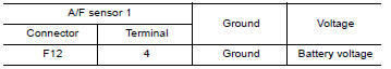
Is the inspection result normal?
YES >> GO TO 9.
NO >> GO TO 8.
8.DETECT MALFUNCTIONING PART
- Check the following.
- IPDM E/R harness connector F42
- 20A fuse (No. 53)
- Harness for open or short between A/F sensor 1 and fuse
>> Repair or replace harness or connectors.
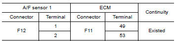
9.CHECK A/F SENSOR 1 INPUT SIGNAL CIRCUIT FOR OPEN AND SHORT
- Turn ignition switch OFF.
- Disconnect ECM harness connector.
- Check the continuity between A/F sensor 1 harness connector and ECM
harness connector.
- Check the continuity between A/F sensor 1 harness connector and ground
or ECM harness connector
and ground.
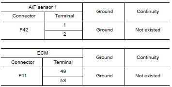
- Also check harness for short to power.
Is the inspection result normal?
YES >> GO TO 10.
NO >> Repair open circuit, short to ground or short to power in harness or connectors.
10.CHECK A/F SENSOR 1 HEATER
Refer to EC, "Component Inspection".
Is the inspection result normal?
YES >> GO TO 11.
NO >> GO TO 13.
11.CHECK HEATED OXYGEN SENSOR 2
Refer to EC, "Component Inspection".
Is the inspection result normal?
YES >> GO TO 12.
NO >> Replace malfunctioning heated oxygen sensor 2.
12.CHECK INTERMITTENT INCIDENT
Perform GI, "Intermittent Incident".
Is the inspection result normal?
YES >> GO TO 13.
NO >> Repair or replace.
13.REPLACE AIR FUEL RATIO (A/F) SENSOR 1
Replace air fuel ratio (A/F) sensor 1. Refer to EM, "Exploded View".
CAUTION:
- Discard any A/F sensor which has been dropped from a height of more than 0.5 m (19.7 in) onto a hard surface such as a concrete floor; use a new one.
- Before installing new A/F sensor, clean exhaust system threads using Oxygen Sensor Thread Cleaner [commercial service tool (J-43897-18 or J-43897-12)] and approved anti-seize lubricant (commercial service tool).
Do you have CONSULT?
YES >> GO TO 14.
NO >> GO TO 15.
14.CONFIRM A/F ADJUSTMENT DATA
With CONSULT
- Turn ignition switch ON.
- Select "A/F ADJ-B1" in "DATA MONITOR" mode with CONSULT.
- Make sure that "0.000" is displayed on CONSULT screen.
Is "0.000" displayed?
YES >> INSPECTION END
NO >> GO TO 15.
15.CLEAR THE MIXTURE RATIO SELF-LEARNING VALUE
Clear the mixture ratio self-learning value. Refer to EC, "Work Procedure".
Do you have CONSULT?
YES >> GO TO 16.
NO >> INSPECTION END
16.CONFIRM A/F ADJUSTMENT DATA
With CONSULT
- Turn ignition switch ON.
- Select "A/F ADJ-B1" in "DATA MONITOR" mode with CONSULT.
- Make sure that "0.000" is displayed on CONSULT screen.
>> INSPECTION END
 P1805 brake switch
Other materials:
Spark plugs
Replacing spark plugs
Platinum-tipped spark plugs
It is not necessary to replace platinum-tipped A
spark plugs as frequently as conventional type
spark plugs because they last much longer. Follow
the maintenance log shown in the Maintenance
and Schedules section of this manual. Do
not ser ...
Engine control system symptoms
Symptom Table
SYSTEM - BASIC ENGINE CONTROL SYSTEM
1 - 6: The numbers refer to the order of inspection.
(continued on next table)
SYSTEM - ENGINE MECHANICAL & OTHER
1 - 6: The numbers refer to the order of inspection. ...
Categories
- Manuals Home
- Nissan Versa Owners Manual
- Nissan Versa Service Manual
- Video Guides
- Questions & Answers
- External Resources
- Latest Updates
- Most Popular
- Sitemap
- Search the site
- Privacy Policy
- Contact Us

0.0074