Nissan Versa (N17): P2100, P2103 throttle control motor relay
DTC Logic
DTC DETECTION LOGIC
| DTC No. | Trouble diagnosis name | DTC detecting condition | Possible cause |
| P2100 | Throttle control motor relay circuit open | ECM detects a voltage of power source for throttle control motor is excessively low. |
|
| P2103 | Throttle control motor relay circuit short | ECM detect the throttle control motor relay is stuck ON. |
|
DTC CONFIRMATION PROCEDURE
1.PRECONDITIONING
If DTC Confirmation Procedure has been previously conducted, always perform the following before conducting the next test.
- Turn ignition switch OFF and wait at least 10 seconds.
- Turn ignition switch ON.
- Turn ignition switch OFF and wait at least 10 seconds.
TESTING CONDITION: Before performing the following procedure, confirm that battery voltage is more than 8 V.
Witch DTC is detected?
P2100 >> GO TO 2.
P2103 >> GO TO 3.
2.PERFORM DTC CONFIRMATION PROCEDURE FOR DTC P2100
- Turn ignition switch ON and wait at least 2 seconds.
- Start engine and let it idle for 5 seconds.
- Check DTC.
Is DTC detected?
YES >> Go to EC, "Diagnosis Procedure".
NO >> INSPECTION END
3.PERFORM DTC CONFIRMATION PROCEDURE FOR DTC P2103
- Turn ignition switch ON and wait at least 1 second.
- Check DTC.
Is DTC detected?
YES >> Go to EC, "Diagnosis Procedure".
NO >> INSPECTION END
Diagnosis Procedure
1.CHECK THROTTLE CONTROL MOTOR RELAY POWER SUPPLY CIRCUIT-I
- Turn ignition switch OFF.
- Check voltage between ECM harness connector and ground
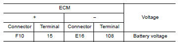
Is the inspection result normal?
YES >> GO TO 5.
NO >> GO TO 2.
2.CHECK THROTTLE CONTROL MOTOR RELAY INPUT SIGNAL CIRCUIT-I
- Disconnect ECM harness connector.
- Disconnect IPDM E/R harness connector F115.
- Check the continuity between ECM harness connector and IPDM E/R harness
connector.
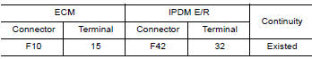
- Also check harness for short to ground and short to power.
Is the inspection result normal?
YES >> GO TO 4.
NO >> GO TO 3.
3.DETECT MALFUNCTIONING PART
Check the following.
- IPDM E/R connector F42
- Harness for open or short between IPDM E/R and ECM
>> Repair open circuit or short to ground or short to power in harness or connectors.
4.CHECK FUSE
- Disconnect 20 A fuse (No. 53) from IPDM E/R.
- Check 20 A fuse for blown.
Is the inspection result normal?
YES >> GO TO 9.
NO >> Replace 20 A fuse.
5.CHECK THROTTLE CONTROL MOTOR RELAY INPUT SIGNAL CIRCUIT-I
- Check voltage between ECM harness connector and ground under the
following conditions.
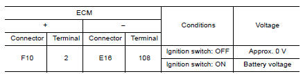
Is the inspection result normal?
YES >> GO TO 8.
NO >> GO TO 6.
6.CHECK THROTTLE CONTROL MOTOR RELAY INPUT SIGNAL CIRCUIT-II
- Turn ignition switch OFF.
- Disconnect ECM harness connector.
- Disconnect IPDM E/R harness connector F42.
- Check the continuity between ECM harness connector and IPDM E/R harness
connector.

- Also check harness for short to ground and short to power.
Is the inspection result normal?
YES >> GO TO 8.
NO >> GO TO 7.
7.DETECT MALFUNCTIONING PART
Check the following.
- IPDM E/R connector F42
- Harness for open or short between IPDM E/R and ECM
>> Repair open circuit or short to ground or short to power in harness or connectors.
8.CHECK FUSE
- Disconnect 15 A fuse (No. 52) from IPDM E/R.
- Check 15 A fuse for blown.
Is the inspection result normal?
YES >> GO TO 9.
NO >> Replace 15 A fuse.
9.CHECK INTERMITTENT INCIDENT
Refer to GI, "Intermittent Incident".
Is the inspection result normal?
YES >> Replace IPDM E/R. Refer to PCS, "Removal and Installation" (WITH I-KEY) or PCS, "Removal and Installation" (WITHOUT I-KEY).
NO >> Repair or replace harness or connectors.
 P2096, P2097 A/F sensor 1
Other materials:
Air cleaner and air duct
Exploded View
1. Clamp 2. PCV hose 3. Clamp
4. Mount rubber 5. Air duct (inlet) 6. Air cleaner body
7. Grommet 8. Air cleaner filter 9. Air cleaner cover
10. Mass air flow sensor 11. Air duct 12. Clamp
Removal and Installation
REMOVAL
NOTE:
Mass air flow sensor is removable as an assemb ...
Adjustment of steering angle sensor
neutral position
Description
Refer to the table below to determine if adjustment of steering angle sensor
neutral position is required.
Work Procedure
ADJUSTMENT OF STEERING ANGLE SENSOR NEUTRAL POSITION
CAUTION:
To adjust neutral position of steering angle sensor, make sure to use CONSULT.
(Adjustme ...
Categories
- Manuals Home
- Nissan Versa Owners Manual
- Nissan Versa Service Manual
- Video Guides
- Questions & Answers
- External Resources
- Latest Updates
- Most Popular
- Sitemap
- Search the site
- Privacy Policy
- Contact Us

0.0052