Nissan Versa (N17): Brake pedal position switch
Component Function Check
1.CHECK BRAKE PEDAL POSITION SWITCH FUNCTION
With CONSULT
- Turn ignition switch ON.
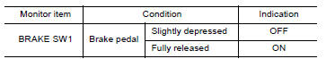
- Select "BRAKE SW1" in "DATA MONITOR" mode of "ENGINE" using CONSULT.
- Check "BRAKE SW1" indication as per the following conditions.
Without CONSULT
- Turn ignition switch ON.
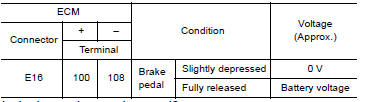
- Check the voltage between ECM harness connector terminals as per the
following.
Is the inspection result normal?
YES >> INSPECTION END
NO >> Proceed to EC, "Diagnosis Procedure".
Diagnosis Procedure
1.CHECK BRAKE PEDAL POSITION SWITCH POWER SUPPLY
- Turn ignition switch OFF.
- Disconnect brake pedal position switch harness connector.
- Turn ignition switch ON.
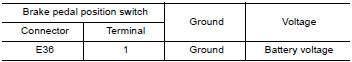
- Check the voltage between brake pedal position switch harness connector
and ground.
Is the inspection result normal?
YES >> GO TO 2.
NO >> Perform the trouble diagnosis for power supply circuit.
2.CHECK BRAKE PEDAL POSITION SWITCH INPUT SIGNAL CIRCUIT
- Turn ignition switch OFF.
- Disconnect ECM harness connector.
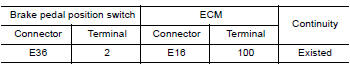
- Check the continuity between brake pedal position switch harness
connector and ECM harness connector.
- Also check harness for short to ground and to power.
Is the inspection result normal?
YES >> GO TO 3.
NO >> Repair or replace error-detected parts.
3.CHECK BRAKE PEDAL POSITION SWITCH
Check the brake pedal position switch. Refer to EC, "Component Inspection (Brake Pedal Position Switch)"
Is the inspection result normal?
YES >> Check intermittent incident. Refer to GI, "Intermittent Incident".
NO >> Replace brake pedal position switch. Refer to BR, "Exploded View".
Component Inspection (Brake Pedal Position Switch)
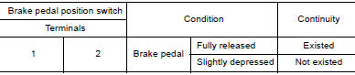
1.CHECK BRAKE PEDAL POSITION SWITCH-I
- Turn ignition switch OFF.
- Disconnect brake pedal position switch harness connector.
- Check the continuity between brake pedal position switch terminals as
per the following conditions.
Is the inspection result normal?
YES >> INSPECTION END
NO >> GO TO 2.
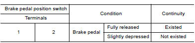
2.CHECK BRAKE PEDAL POSITION SWITCH-II
- Adjust brake pedal position switch installation. Refer to BR, "Inspection and Adjustment".
- Check the continuity between brake pedal position switch terminals as
per the following conditions.
Is the inspection result normal?
YES >> INSPECTION END
NO >> Replace brake pedal position switch. Refer to BR, "Exploded View".
 P2138 APP sensor
Clutch pedal position switch
Component Function Check 1.CHECK CLUTCH PEDAL POSITION SWITCH FUNCTION Turn ignition switch ON. Check the voltage between ECM harness connector and ground. Is the inspection result ...
Other materials:
Line pressure control
LINE PRESSURE CONTROL : System Description
SYSTEM DIAGRAM
DESCRIPTION
Highly accurate line pressure control (secondary pressure control) reduces
friction for improvement of fuel
economy.
Normal Oil Pressure Control
Appropriate line pressure and secondary pressure suitable for driving
c ...
SRS Air bag system
SRS AIR BAG SYSTEM : System Diagram
SRS AIR BAG SYSTEM : System Description
The air bag deploys if the air bag diagnosis sensor unit is activated
while the ignition switch is in the ON or
START position.
The collision modes for which supplemental restraint systems are
activated a ...
Categories
- Manuals Home
- Nissan Versa Owners Manual
- Nissan Versa Service Manual
- Video Guides
- Questions & Answers
- External Resources
- Latest Updates
- Most Popular
- Sitemap
- Search the site
- Privacy Policy
- Contact Us

0.0103