Nissan Versa (N17): Cooling fan
Component Function Check
1.CHECK COOLING FAN FUNCTION
With CONSULT
- Turn ignition switch ON.
- Perform "COOLING FAN" in "ACTIVE TEST" mode with CONSULT.
- Touch "LOW" and "Hi" on the CONSULT screen.
- Check that cooling fan operates.
NOTE: The cooling fan operates at high speeds even when "LOW" is selected in CONSULT "ACTIVE TEST". (For single connector cooling fan without A/C models)
Without CONSULT
- Perform IPDM E/R auto active test and check cooling fan motor operation. Refer to PCS, "Diagnosis Description".
- Check that cooling fan operates.
Is the inspection result normal?
YES >> INSPECTION END
NO >> Refer to EC, "Diagnosis Procedure".
Diagnosis Procedure
FOR SINGLE CONNECTOR COOLING FAN WITHOUT A/C MODELS
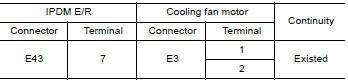
1.CHECK COOLING FAN MOTOR CIRCUIT
- Disconnect cooling fan motor harness connector.
- Check the continuity between IPDM E/R harness connector and cooling fan
motor harness connector.
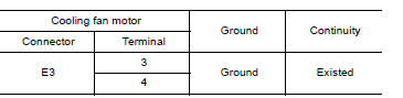
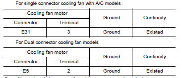
- Check the continuity between cooling fan motor harness connector and
ground.
- Also check harness for short to ground and short to power.
Is the inspection result normal?
YES >> GO TO 2.
NO >> Repair open circuit or short to ground or short to power in harness or connectors.
2.CHECK COOLING FAN MOTOR
Refer to EC, "Component Inspection (Cooling Fan Motor)".
Is the inspection result normal?
YES >> GO TO 3.
NO >> Replace cooling fan motor. Refer to CO, "Removal and Installation".
3.CHECK INTERMITTENT INCIDENT
Perform GI, "Intermittent Incident".
Is the inspection result normal?
YES >> Replace IPDM E/R. Refer to PCS, "Removal and Installation" (WITH I-KEY) or PCS, "Removal and Installation" (WITHOUT I-KEY).
NO >> Repair or replace harness or connector.
EXCEPT FOR SINGLE CONNECTOR COOLING FAN WITHOUT A/C MODELS
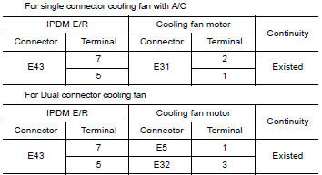
1.CHECK COOLING FAN MOTOR CIRCUIT
- Disconnect cooling fan motor harness connector.
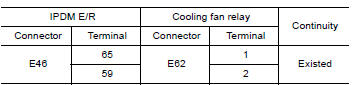
- Check the continuity between IPDM E/R harness connector and cooling fan
motor harness connector.
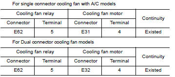
- Check the continuity between cooling fan relay harness connector and
cooling fan motor harness connector.
- Check the continuity between cooling fan motor harness connector and
ground.
- Also check harness for short to ground and short to power.
Is the inspection result normal?
YES >> GO TO 2.
NO >> Repair open circuit or short to ground or short to power in harness or connectors.
2.CHECK COOLING FAN RELAY CIRCUIT
- Disconnect cooling fan relay harness connector.
- Disconnect IPDM E/R harness connector.
- Check the continuity between IPDM E/R harness connector and cooling fan
relay harness connector.
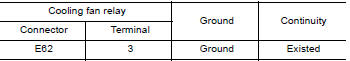
- Check the continuity between cooling fan relay harness connector and
ground.
- Also check harness for short to ground and short to power.
Is the inspection result normal?
YES >> GO TO 3.
NO >> Repair open circuit or short to ground or short to power in harness or connectors.
3.CHECK COOLING FAN RELAY
Refer to EC, "Component Inspection (Cooling Fan Relay)".
YES or NO
YES >> GO TO 4.
NO >> Replace cooling fan relay.
4.CHECK COOLING FAN MOTOR
Refer to EC, "Component Inspection (Cooling Fan Motor)".
YES or NO
YES >> GO TO 5.
NO >> Replace cooling fan motor. Refer to CO, "Removal and Installation".
5.CHECK INTERMITTENT INCIDENT
Perform GI, "Intermittent Incident".
YES or NO
YES >> Replace IPDM E/R. Refer to PCS, "Removal and Installation" (WITH I-KEY) or PCS, "Removal and Installation" (WITHOUT I-KEY).
NO >> Repair or replace harness or connector.
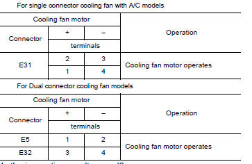
Component Inspection (Cooling Fan Motor)
1.CHECK COOLING FAN MOTOR
- Turn ignition switch OFF.
- Disconnect cooling fan motor harness connector.
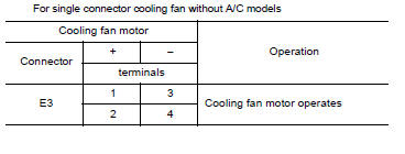
- Supply cooling fan motor terminals with battery voltage and check
operation.
Is the inspection result normal?
YES >> INSPECTION END
NO >> Replace cooling fan motor. Refer to CO, "Removal and Installation".
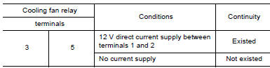
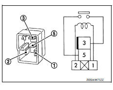
Component Inspection (Cooling Fan Relay)
1.CHECK COOLING FAN RELAY
- Turn ignition switch OFF.
- Remove cooling fan relay.
- Check continuity between cooling fan relay terminals under the
following conditions.
Is the inspection result normal?
YES >> INSPECTION END
NO >> Replace cooling fan relay.
 Clutch pedal position switch
Component Function Check 1.CHECK CLUTCH PEDAL POSITION SWITCH FUNCTION Turn ignition switch ON. Check the voltage between ECM harness connector and ground. Is the inspection result ...
Electrical load signal
Description The electrical load signal (Headlamp switch signal, rear window defogger switch signal, etc.) is transferred to ECM through the CAN communication line. ...
Other materials:
Reporting safety defects
For USA
If you believe that your vehicle has a defect
which could cause a crash or could
cause injury or death, you should immediately
inform the National Highway Traffic
Safety Administration (NHTSA) in addition
to notifying NISSAN.
If NHTSA receives similar complaints, it
may open an inv ...
Differential side oil seal
Exploded View
1. Transaxle assembly 2. Differential side oil seal (left side) 3.
Differential side oil seal (right side)
Front Genuine
NISSAN CVT Fluid NS-3
Removal and Installation
NOTE:
When removing components such as hoses, tubes/lines, etc., cap or plug openings
to prevent flui ...
Categories
- Manuals Home
- Nissan Versa Owners Manual
- Nissan Versa Service Manual
- Video Guides
- Questions & Answers
- External Resources
- Latest Updates
- Most Popular
- Sitemap
- Search the site
- Privacy Policy
- Contact Us

0.0062