Nissan Versa (N17): Electrical load signal
Description
The electrical load signal (Headlamp switch signal, rear window defogger switch signal, etc.) is transferred to ECM through the CAN communication line.
Component Function Check
1.CHECK REAR WINDOW DEFOGGER SWITCH FUNCTION
- Turn ignition switch ON.
- Select "DATA MONITOR" mode with CONSULT.
- Select "LOAD SIGNAL" and check indication under the following
conditions.
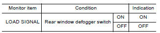
Is the inspection result normal?
YES >> GO TO 2.
NO >> Go to EC, "Diagnosis Procedure".
2.CHECK LIGHTING SWITCH FUNCTION
Check "LOAD SIGNAL" indication under the following conditions.
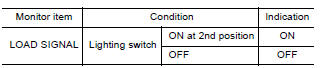
Is the inspection result normal?
YES >> GO TO 3.
NO >> Go to EC, "Diagnosis Procedure".
3.CHECK HEATER FAN CONTROL SWITCH FUNCTION
Select "HEATER FAN SW" and check indication under the following conditions
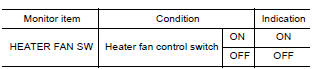
Is the inspection result normal?
YES >> INSPECTION END
NO >> Go to EC, "Diagnosis Procedure".
Diagnosis Procedure
1.INSPECTION START
Confirm the malfunctioning circuit (rear window defogger, headlamp or heater fan). Refer to EC, "Component Function Check".
Which circuit is related to the incident?
Rear window defogger>>GO TO 2
Headlamp>>GO TO 3.
Heater fan>>GO TO 4.
2.CHECK REAR WINDOW DEFOGGER SYSTEM
Perform trouble diagnosis of rear window defogger system. Refer to DEF, "Work Flow".
>> INSPECTION END
3.CHECK HEADLAMP SYSTEM
Perform trouble diagnosis of headlamp system. Refer to EXL, "Work Flow".
>> INSPECTION END
4.CHECK AIR CONDITIONING SYSTEM
Perform trouble diagnosis of air conditioning system. Refer to HA, "Workflow".
>> INSPECTION END
 Cooling fan
Other materials:
P074B Unable to engage 3GR
Description
This malfunction is detected when the A/T does not shift into 3GR position as
instructed by TCM. This is not
only caused by electrical malfunction (circuits open or shorted) but by
mechanical malfunction such as control
valve sticking, improper solenoid valve operation, etc.
DTC ...
P0963 Pressure control solenoid A
DTC Logic
DTC DETECTION LOGIC
DTC
Trouble diagnosis name
DTC detection condition
Possible causes
P0963
Pressure Control Solenoid "A"
Control Circuit High
The following diagnosis conditions
are met, and the current
monitor reading of the TCM line
pressure ...
Categories
- Manuals Home
- Nissan Versa Owners Manual
- Nissan Versa Service Manual
- Video Guides
- Questions & Answers
- External Resources
- Latest Updates
- Most Popular
- Sitemap
- Search the site
- Privacy Policy
- Contact Us

0.0053