Nissan Versa (N17): Fuel injector
Component Function Check
1.INSPECTION START
Turn ignition switch to START.
Is any cylinder ignited?
YES >> GO TO 2.
NO >> Go to EC, "Diagnosis Procedure".
2.CHECK FUEL INJECTOR FUNCTION
With CONSULT
- Start engine.
- Perform "POWER BALANCE" in "ACTIVE TEST" mode with CONSULT.
- Make sure that each circuit produces a momentary engine speed drop.
Without CONSULT
- Let engine idle.
- Listen to each fuel injector operating sound.
Clicking noise should be heard.
Is the inspection result normal?
YES >> INSPECTION END
NO >> Go to EC, "Diagnosis Procedure".
Diagnosis Procedure
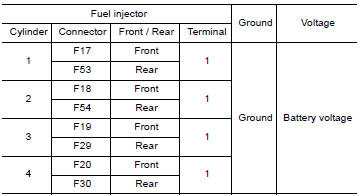
1.CHECK FUEL INJECTOR POWER SUPPLY CIRCUIT
- Turn ignition switch OFF.
- Disconnect fuel injector harness connector.
- Turn ignition switch ON.
- Check the voltage between fuel injector harness connector and ground.
Is the inspection result normal?
YES >> GO TO 3.
NO >> GO TO 2.
2.DETECT MALFUNCTIONING PART
Check the following.
- IPDM E/R connector F42
- 10 A fuse (No. 55)
- Harness for open or short between fuel injector and fuse
>> Repair open circuit or short to ground or short to power in harness or connectors.
3.CHECK FUEL INJECTOR OUTPUT SIGNAL CIRCUIT FOR OPEN AND SHORT
- Turn ignition switch OFF.
- Disconnect ECM harness connector.
- Check the continuity between fuel injector harness connector and ECM
harness connector.
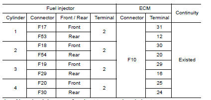
- Also check harness for short to ground and short to power.
Is the inspection result normal?
YES >> GO TO 4.
NO >> Repair open circuit or short to ground or short to power in harness or connectors.
4.CHECK FUEL INJECTOR
Refer to EC, "Component Inspection".
Is the inspection result normal?
YES >> GO TO 5.
NO >> Replace malfunctioning fuel injector. Refer to EM, "Removal and Installation"
5.CHECK INTERMITTENT INCIDENT
Refer to GI, "Intermittent Incident".
Is the inspection result normal?
YES >> Replace IPDM E/R. Refer to PCS, "Removal and Installation" (WITH I-KEY) or PCS, "Removal and Installation" (WITHOUT I-KEY).
NO >> Repair or replace harness or connectors.
Component Inspection
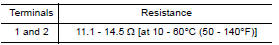
1.CHECK FUEL INJECTOR
- Turn ignition switch OFF.
- Disconnect fuel injector harness connector.
- Check resistance between fuel injector terminals as follows.
Is the inspection result normal?
YES >> INSPECTION END
NO >> Replace malfunctioning fuel injector. Refer to EM, "Removal and Installation".
 Electrical load signal
Description The electrical load signal (Headlamp switch signal, rear window defogger switch signal, etc.) is transferred to ECM through the CAN communication line. ...

Other materials:
Bluetooth Hands-Free Phone System with Navigation System (if so equipped)
WARNING
Use a phone after stopping your vehicle
in a safe location. If you have to use a
phone while driving, exercise extreme
caution at all times so full attention may
be given to vehicle operation.
If you are unable to devote full attention
to vehicle operation while talking on
...
If your vehicle overheats
If your vehicle is overheating (indicated by an
extremely high temperature gauge reading (if so
equipped), a red high temperature warning light
(if so equipped) ), or if you feel a
lack of
engine power, detect abnormal noise, etc. take
the following steps.
WARNING
Do not continue to driv ...
Categories
- Manuals Home
- Nissan Versa Owners Manual
- Nissan Versa Service Manual
- Video Guides
- Questions & Answers
- External Resources
- Latest Updates
- Most Popular
- Sitemap
- Search the site
- Privacy Policy
- Contact Us

0.0052