Nissan Versa (N17): Fuel pump
Component Function Check
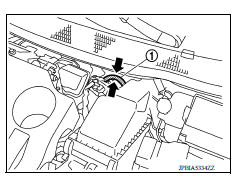
1.CHECK FUEL PUMP FUNCTION
- Turn ignition switch ON.
- Pinch fuel feed hose (1) with two fingers.
Fuel pressure pulsation should be felt on the fuel feed hose for 1 second after ignition switch is turned ON.
Is the inspection result normal?
YES >> INSPECTION END
NO >> EC, "Diagnosis Procedure".
Diagnosis Procedure
1.CHECK FUEL PUMP POWER SUPPLY CIRCUIT-I
- Turn ignition switch OFF.
- Disconnect ECM harness connector.
- Turn ignition switch ON.
- Check the voltage between ECM harness connector and ground.
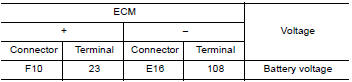
Is the inspection result normal?
YES >> GO TO 3.
NO >> GO TO 2.
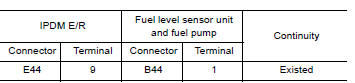
2.CHECK FUEL PUMP POWER SUPPLY CIRCUIT-II
- Turn ignition switch OFF.
- Disconnect IPDM E/R harness connector.
- Check the continuity between IPDM E/R harness connector and ECM harness
connector.
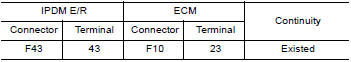
- Also check harness for short to ground and short to power.
Is the inspection result normal?
YES >> GO TO 8.
NO >> Repair open circuit or short to ground or short to power in harness or connectors.
3.CHECK FUEL PUMP POWER SUPPLY CIRCUIT-III
- Turn ignition switch OFF.
- Reconnect all harness connectors disconnected.
- Disconnect "fuel level sensor unit and fuel pump" harness connector.
- Turn ignition switch ON.
- Check the voltage between "fuel level sensor unit and fuel pump" harness
connector and ground.
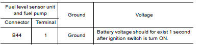
Is the inspection result normal?
YES >> GO TO 6.
NO >> GO TO 4.
4.CHECK FUSE
- Turn ignition switch OFF.
- Disconnect 15 A fuse (No. 48) from IPDM E/R.
- Check 15 A fuse.
Is the inspection result normal?
YES >> GO TO 5.
NO >> Replace 15 A fuse.
5.CHECK FUEL PUMP POWER SUPPLY CIRCUIT-IV
- Turn ignition switch OFF.
- Disconnect IPDM E/R harness connector.
- Check the continuity between IPDM E/R harness connector and "fuel level
sensor unit and fuel pump"
harness connector.
- Also check harness for short to ground and short to power.
Is the inspection result normal?
YES >> GO TO 6.
NO >> Repair open circuit, short to ground or short to power in harness or connectors.
6.CHECK FUEL PUMP GROUND CIRCUIT FOR OPEN AND SHORT
- Turn ignition switch OFF.
- Check the continuity between "fuel level sensor unit and fuel pump"
harness connector and ground.
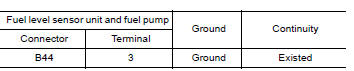
- Also check harness for short to power.
Is the inspection result normal?
YES >> GO TO 7.
NO >> Repair open circuit or short to power in harness or connectors.
7.CHECK FUEL PUMP
Refer to EC, "Component Inspection".
Is the inspection result normal?
YES >> GO TO 8.
NO >> Replace "fuel level sensor unit and fuel pump".Refer to FL, "Exploded View".
8.CHECK INTERMITTENT INCIDENT
Check intermittent incident. Refer to GI, "Intermittent Incident".
Is the inspection result normal?
YES >> Replace IPDM E/R. Refer to PCS, "Removal and Installation" (WITH I-KEY) or PCS, "Removal and Installation" (WITHOUT I-KEY).
NO >> Repair open circuit, short to ground or short to power in harness or connectors.
Component Inspection
1.CHECK FUEL PUMP
- Turn ignition switch OFF.
- Disconnect "fuel level sensor unit and fuel pump" harness connector.
- Check resistance between "fuel level sensor unit and fuel pump"
terminals as follows.
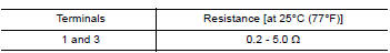
Is the inspection result normal?
YES >> INSPECTION END
NO >> Replace "fuel level sensor unit and fuel pump". Refer to FL, "Exploded View".
 Fuel injector
Other materials:
Security systems (if so equipped)
Your vehicle has one type of security systems:
NISSAN Vehicle Immobilizer System
NISSAN vehicle immobilizer system
The NISSAN Vehicle Immobilizer System will not
allow the engine to start without the use of a
registered key.
If the engine fails to start using a registered key
(for ex ...
ABS Warning lamp
Component Function Check
1.CHECK ABS WARNING LAMP FUNCTION
Check that ABS warning lamp in combination meter turns ON for approximately 2
seconds after ignition switch
is turned ON.
Is the inspection result normal?
YES >> Inspection End.
NO >> Proceed to diagnosis procedure. Ref ...
Categories
- Manuals Home
- Nissan Versa Owners Manual
- Nissan Versa Service Manual
- Video Guides
- Questions & Answers
- External Resources
- Latest Updates
- Most Popular
- Sitemap
- Search the site
- Privacy Policy
- Contact Us

0.0063