Nissan Versa (N17): P0713 Transmission fluid temperature sensor A
DTC Logic
DTC DETECTION LOGIC
| DTC | Trouble diagnosis name | DTC detection condition | Possible causes |
| P0713 | Transmission Fluid Temperature Sensor A Circuit High | The CVT fluid temperature identified by the
TCM is −40C (−40F) or less continuously for
5 seconds or more under the following diagnosis
conditions: - Diagnosis conditions - Ignition switch: ON - Vehicle speed: More than 10 km/h (7 MPH) - TCM power supply voltage: More than 11 V |
- Harness or connector
(CVT fluid temperature sensor circuit is
open or shorted to power supply) - CVT fluid temperature sensor |
DTC CONFIRMATION PROCEDURE
1.PREPARATION BEFORE WORK
If another "DTC CONFIRMATION PROCEDURE" occurs just before, turn ignition switch OFF and wait for at least 10 seconds, then perform the next test.
>> GO TO 2.
2.PERFORM DTC CONFIRMATION PROCEDURE
- Start the engine.
- Maintain the following condition for 10 seconds or more.
- Stop the vehicle.
- Check the first trip DTC.
Vehicle speed : 20 km/h (12 MPH) or more
Is "P0713" detected?
YES >> Go to TM "Diagnosis Procedure".
NO >> INSPECTION END
Diagnosis Procedure
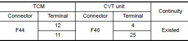
1.CHECK CIRCUIT BETWEEN TCM AND CVT UNIT (PART 1)
- Turn ignition switch OFF.
- Disconnect TCM connector and CVT unit connector.
- Check continuity between TCM harness connector terminals and CVT unit
harness connector terminals.
Is the inspection result normal?
YES >> GO TO 2.
NO >> Repair or replace malfunctioning part.
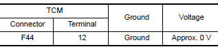
2.CHECK CIRCUIT BETWEEN TCM AND CVT UNIT (PART 2)
- Turn ignition switch ON.
- Check voltage between TCM harness connector terminal and ground.
Is the inspection result normal?
YES >> GO TO 3.
NO >> Repair or replace malfunctioning part.
3.CHECK CVT FLUID TEMPERATURE SENSOR
Check CVT fluid temperature sensor. Refer to TM "Component Inspection (CVT Fluid Temperature Sensor)".
Is the inspection result normal?
YES >> Check intermittent incident. Refer to GI "Intermittent Incident".
NO >> Repair or replace malfunctioning parts.
Component Inspection (CVT Fluid Temperature Sensor)
1.CHECK CVT FLUID TEMPERATURE SENSOR
Check resistance between CVT unit connector terminals. 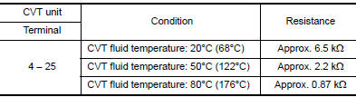
Is the inspection result normal?
YES >> INSPECTION END
NO >> There is a malfunction of CVT fluid temperature sensor. Replace transaxle assembly. Refer to TM "Removal and Installation".
 P0712 Transmission fluid temperature
sensor A
P0712 Transmission fluid temperature
sensor A
DTC Logic DTC DETECTION LOGIC DTC Trouble diagnosis name DTC detection condition Possible causes P0712 Transmission Fluid Temperature Sensor A Circuit Low The CVT ...

Other materials:
Service data and specifications
(SDS)
Idle Speed
*: Under the following conditions
A/C switch: OFF
Electric load: OFF (Lights, heater fan & rear window defogger)
Steering wheel: Kept in straight-ahead position
Ignition Timing
*: Under the following conditions
A/C switch: OFF
Ele ...
Control linkage
Exploded View
1. Shifter lever A 2. Selector lever 3. Selector cable
4. Shifter cable 5. Cable mounting bracket 6. Tapping bolt
7. Bracket 8. Grommet 9. M/T shift selector assembly
10. Shift selector 11. Shift selector handle
Removal and Installation
REMOVAL
Move the shift selector to ...
Categories
- Manuals Home
- Nissan Versa Owners Manual
- Nissan Versa Service Manual
- Video Guides
- Questions & Answers
- External Resources
- Latest Updates
- Most Popular
- Sitemap
- Search the site
- Privacy Policy
- Contact Us

0.0074