Nissan Versa (N17): Vacuum lines
Exploded View
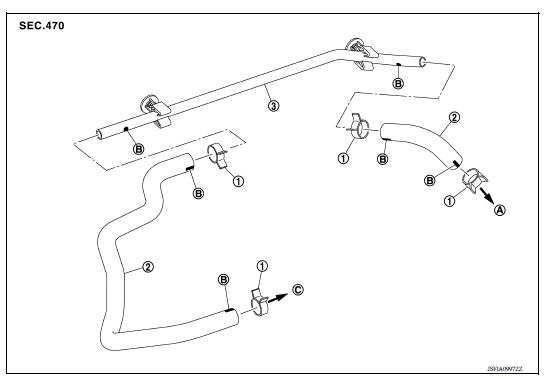
1. Clamp 2. Vacuum hose 3. Vacuum piping A. To brake booster B. Paint mark C. To intake manifold
Removal and Installation
REMOVAL
- Remove the air cleaner and duct assembly. Refer to EM "Exploded View".
- Remove the vacuum hose and vacuum piping.
INSTALLATION
Installation is in the reverse order of removal.
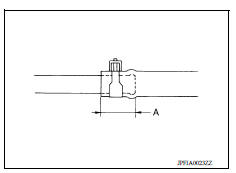
- When installing vacuum hose, insert it until its tip reaches the
back-end of length (A) or further as shown.
CAUTION: Do not use lubricating oil during assembly.
(A) : 24 mm (0.95 in) or more
- Face the paint mark of vacuum hose (intake manifold side) upward to assemble.
- Face the other paint marks of vacuum hose to the vehicle front side to assemble.
Inspection
INSPECTION AFTER REMOVAL
Appearance
Check for correct assembly, damage and deterioration.
FRONT DISC BRAKE
 Brake booster and check valve
Exploded View 1. Master cylinder assembly 2. Check valve 3. Brake booster 4. Lock nut 5. Clevis 6. Gasket ...
Brake pad
BRAKE PAD : Exploded View 1. Cylinder body 2. Inner shim 3. Inner pad (with pad wear sensor) 4. Pad return spring 5. Pad retainer 6. Torque member 7. Outer pad 8. Outer shim : Apply MOLYKOTE 7 ...
Other materials:
P0705 Transmission range switch A
DTC Logic
DTC DETECTION LOGIC
DTC
Trouble diagnosis name
DTC detection condition
Possible causes
P0705
Transmission Range Sensor
"A" Circuit Malfunction (PRNDL
input)
The following diagnosis conditions
are met and 2 or more position
signals are ON at the
...
U1000 Can COMM circuit
Description
CAN (Controller Area Network) is a serial communication line for real-time
application. It is an on-vehicle multiplex
communication line with high data communication speed and excellent malfunction
detection ability.
Many electronic control units are equipped onto a vehicle, an ...
Categories
- Manuals Home
- Nissan Versa Owners Manual
- Nissan Versa Service Manual
- Video Guides
- Questions & Answers
- External Resources
- Latest Updates
- Most Popular
- Sitemap
- Search the site
- Privacy Policy
- Contact Us

0.0047