Nissan Versa (N17): C1143 Steering angle sensor
DTC Logic
DTC DETECTION LOGIC 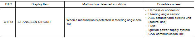
DTC CONFIRMATION PROCEDURE
1.CHECK SELF DIAGNOSTIC RESULT
With CONSULT.
- Turn ignition switch ON.
- Perform self diagnostic result.
Is DTC C1143 detected?
YES >> Proceed to diagnosis procedure. Refer to BRC"Diagnosis Procedure".
NO >> Inspection End.
Diagnosis Procedure
Regarding Wiring Diagram information, refer to BRC-45, "Wiring Diagram".
1.CONNECTOR INSPECTION
- Turn ignition switch OFF.
- Disconnect ABS actuator and electric unit (control unit) and steering angle sensor connectors.
- Check connectors and terminals for deformation, disconnection, looseness or damage.
Is the inspection result normal?
YES >> GO TO 2
NO >> Repair or replace as necessary.
2.CHECK STEERING ANGLE SENSOR MOUNTING CONDITION
Check steering angle sensor mounting condition.
Is the inspection result normal?
YES >> GO TO 3.
NO >> Repair or replace malfunctioning components.
3.CHECK STEERING ANGLE SENSOR POWER SUPPLY
- Turn ignition switch OFF.
- Disconnect steering angle sensor connector.
- Turn ignition switch ON.
- Check voltage between steering angle sensor connector M64 terminal 4 and
ground.
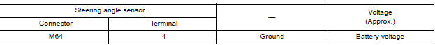
Is the inspection result normal?
YES >> GO TO 5.
NO >> GO TO 4.
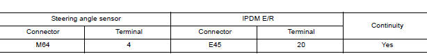
4.CHECK STEERING ANGLE SENSOR POWER SUPPLY CIRCUIT
- Turn ignition switch OFF.
- Disconnect IPDM E/R connector E45.
- Check continuity between steering angle sensor connector M64 terminal 4
and IPDM E/R connector E45
terminal 20.
4. Check continuity between steering angle
sensor connector M64 terminal 4 and ground. 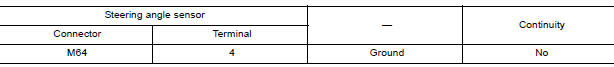
Is the inspection result normal?
YES >> Perform trouble diagnosis for ignition power supply. Refer to PG "Wiring Diagram - Ignition Power Supply -".
NO >> Repair or replace malfunctioning components.
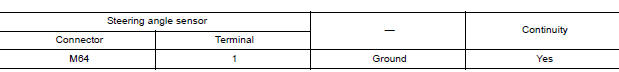
5.CHECK STEERING ANGLE SENSOR GROUND CIRCUIT
- Turn ignition switch OFF.
- Check continuity between steering angle sensor connector M64 terminal 1
and ground.
Is the inspection result normal?
YES >> GO TO 6.
NO >> Repair or replace malfunctioning components.
6.CHECK CAN COMMUNICATION LINE
Check "STRG BRANCH LINE CIRCUIT". Refer to BRC "Diagnosis Procedure" (type 1) or BRC"Diagnosis Procedure" (type 2).
Is the inspection result normal?
YES >> Replace ABS actuator and electric unit (control unit). Refer to BRC "Removal and Installation".
NO >> Repair or replace malfunctioning components.
 C1142 Press sensor
Other materials:
Engine compartment check locations
HR16DE Engine
1. Drive belt location
2. Engine oil filler cap
3. Air cleaner
4. Brake and clutch (if so equipped) fluid
reservoir
5. Fusible link
6. Battery
7. Engine coolant reservoir
8. Radiator cap
9. Engine oil dipstick
10. Windshield-washer fluid reservoir
Refer to the page numb ...
Noise, vibration and harshness (NVH) troubleshooting
NVH troubleshooting Chart
Locate the area where noise occurs.
Confirm the type of noise.
Specify the operating condition of engine.
Check specified noise source
If necessary, repair or replace these parts.
Location
of noise
Type of
noise
Operating condition of
...
Categories
- Manuals Home
- Nissan Versa Owners Manual
- Nissan Versa Service Manual
- Video Guides
- Questions & Answers
- External Resources
- Latest Updates
- Most Popular
- Sitemap
- Search the site
- Privacy Policy
- Contact Us

0.0057