Nissan Versa (N17): EPS Control unit
Exploded View
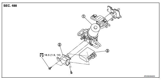
1. Steering column assembly 2. Bracket 3. EPS control unit
Removal and Installation
REMOVAL
- Perform a CPU memory erase on the EPS with CONSULT before removal.
CAUTION:
- Disconnect battery negative terminal before continuing.
- Do not shock EPS control unit, e.g. drop or hit.
- Do not get EPS control unit wet with water or other liquid. Also, do not give EPS control unit a radical temperature change to avoid getting water drops.
- Do not disassemble or remodel EPS control unit, EPS motor, torque sensor, harness and connectors.
- Remove instrument lower panel LH. Refer to IP "Removal and Installation".
- Disconnect harness connectors from EPS control unit.
CAUTION: Hold and pull the connector housing, do not pull on harness when disconnecting connectors.
Also, do not grip, collapse or apply excessive force to the connector.
- Remove EPS control unit from steering column assembly.
- Remove bracket from steering column assembly if necessary.
INSTALLATION
Installation is in the reverse order of removal.
- Check that harness is not damaged when installing EPS control unit. Also, check that EPS control unit is installed without trapping harness on foreign materials.
- After installing steering column assembly, perform self-diagnosis with CONSULT to ensure correct operation.
 Unbalance steering wheel turning force (torque variation)
Description Unbalance steering wheel turning force (torque variation). Diagnosis Procedure 1.PERFORM SELF-DIAGNOSIS With CONSULT Turn the ignition switch OFF to ON. Perform "EPS" self-diagn ...

Other materials:
NISSAN Voice Recognition System (if so equipped)
The NISSAN Voice Recognition system allows
hands-free operation of the systems equipped on
this vehicle, such as the phone and navigation
systems.
To operate NISSAN Voice Recognition, press
the button located on the steering
wheel.
When prompted, speak the command for the
system you wi ...
P0720 Output speed sensor
DTC Logic
DTC DETECTION LOGIC
DTC
Trouble diagnosis name
DTC detection condition
Possible causes
P0720
Output Speed Sensor Circuit
Under the following diagnosis
conditions, the output speed
sensor value is less than 100
rpm continuously for 5 seconds
or ...
Categories
- Manuals Home
- Nissan Versa Owners Manual
- Nissan Versa Service Manual
- Video Guides
- Questions & Answers
- External Resources
- Latest Updates
- Most Popular
- Sitemap
- Search the site
- Privacy Policy
- Contact Us

0.0048