
Nissan Versa (N17): Front coil spring and strut
Exploded View
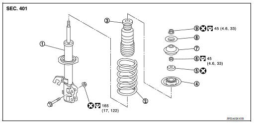
1. Strut assembly 2. Coil spring 3. Bound bumper 4. Spring upper seat 5. Strut mounting bearing 6. Piston rod lock nut 7. Strut mounting insulator 8. Stopper insulator 9. Stopper insulator lock nut
Removal and Installation
REMOVAL
- Remove the wheel and tire assembly using power tool. Refer to WT "Adjustment".
- Remove brake hose lock plate from strut assembly.
- Remove stabilizer connecting rod from strut assembly. Refer to FSU "Removal and Installation".
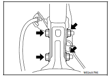
- Remove strut bolts and nuts from steering knuckle.
- Remove stopper insulator lock nut and stopper insulator.
- Remove strut assembly.
INSTALLATION
Installation is in the reverse order of removal.
- Secure the head of strut piston rod to keep it from rotating, then
tighten the stopper insulator lock nut to the
specified torque.
CAUTION: Do not reuse stopper insulator lock nut.
- Do not reuse the nuts that secure the strut to the steering knuckle and stopper insulator lock nut.
- Perform inspection after installation. Refer to FSU "Inspection and Adjustment".
- After replacing the strut assembly, always follow the disposal procedure to discard the strut assembly. Refer to FSU "Disposal".
Disassembly and Assembly
DISASSEMBLY
CAUTION: Do not damage strut assembly piston rod when removing components from strut assembly.
- Remove strut mounting insulator.
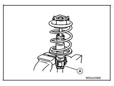
- Install Tool (A) to strut assembly and secure it in a vise.
Tool number : ST35652000 ( - )
CAUTION: When installing the Tool to strut assembly, wrap a shop cloth around strut to protect from damage.
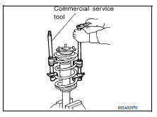
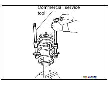
- Using a suitable tool, compress coil spring between spring upper
seat and lower seat (strut assembly) until coil spring is free.
CAUTION: Be sure the tool is securely attached to the coil spring before compressing coil spring.
- Check coil spring with a spring compressor between spring upper seat and lower seat (strut assembly) is free. And then remove piston rod lock nut while securing the piston rod tip so that piston rod does not turn.
- Remove strut mounting bearing, spring upper seat, and bound bumper as a set.
- Remove bound bumper from spring upper seat.
- After removing coil spring with a spring compressor, then gradually
release a spring compressor.
CAUTION: Loosen while making sure coil spring attachment position does not move.
- Remove the Tool from strut.
Tool number : ST35652000 ( - )
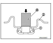
9. If necessary, remove strut mounting bearing (1) from spring upper seat (2), using a Tool (A).
Tool number : KV10106700 ( - )
CAUTION: Do not disassemble the strut mounting bearing unless damage exists.
10. Perform inspection after disassembly. Refer to FSU "Inspection and Adjustment".
INSPECTION AFTER DISASSEMBLY
Strut Inspection
Check the following:
- Strut for deformation, cracks or damage, and replace it if necessary.
- Piston rod for damage, uneven wear or distortion, and replace it if necessary.
- For oil leakage, and replace it if necessary.
Strut Mounting Insulator and Rubber Parts Inspection
Check strut mounting insulator for cracks and rubber parts for wear. Replace it if malfunction is detected.
Coil Spring Inspection
Check coil spring for cracks, wear or damage, and replace it if necessary.
ASSEMBLY
1. Install Tool (A) to strut and secure it in a vise.
Tool number : ST35652000 ( - )
CAUTION: When installing the strut attachment to strut assembly, wrap a shop cloth around strut to protect from damage.
2. Apply soapy water to bound bumper.
CAUTION: Do not use machine oil.
3. Insert bound bumper into spring upper seat.
4. Compress coil spring using a spring compressor (commercial service tool), and install it onto strut assembly.
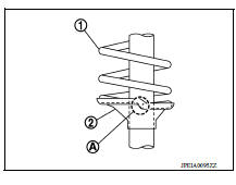
CAUTION:
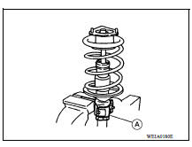
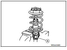
- Face tube side of coil spring (1) downward. Align the lower end (A) to lower seat (strut assembly) (2).
- Be sure a compressor is securely attached to coil spring.
Compress coil spring.
5. Install strut mounting bearing, spring upper seat, and bound bumper as a set.
6. Secure piston rod tip so that piston rod does not turn, then tighten piston rod lock nut with specified torque.
7. Gradually release a spring compressor, and remove coil spring.
CAUTION: Loosen while making sure coil spring attachment position does not move.
8. Remove the Tool (A) from strut assembly.
Tool number : ST35652000 ( - )
9. Install strut mounting insulator.
Disposal
- Set strut assembly horizontally to the ground with the piston rod fully extracted.
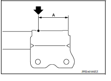
- Drill 2 - 3 mm (0.08 - 0.12 in) hole at the position (
 ) from top
as shown to release gas gradually.
) from top
as shown to release gas gradually.
CAUTION:
- Wear eye protection (safety glass).
- Wear gloves.
- Be careful with metal chips or oil blown out by the compressed gas.
NOTE:
- Drill vertically in this direction.
- Directly to the outer tube avoiding brackets.
- The gas is clear, colorless, odorless, and harmless.
(A) : 20 - 30 mm (0.79 - 1.18 in)
3. Position the drilled hole downward and drain oil by moving the piston rod several times.
CAUTION: Dispose of drained oil according to the law and local regulations.
 Front suspension assembly
Inspection and Adjustment INSPECTION Make sure the mounting conditions (looseness, back lash) of each component and component conditions (wear, damage) are normal. LOWER BALL JOINT END PLAY ...
Transverse link
Exploded View 1. Front suspension member 2. Transverse link Removal and Installation REMOVAL Remove the wheel and tire assembly using power tool. Refer to WT "Adjustment". ...
Other materials:
RearView Monitor (if so equipped)
1. CAMERA button (models with navigation)
WARNING
Failure to follow the warnings and instructions
for proper use of the Rear-
View Monitor system could result in serious
injury or death.
RearView Monitor is a convenience feature
and is not a substitute for proper
backing. Always ...
IDLE SPEED
Inspection
1.CHECK IDLE SPEED
With CONSULT
Check idle speed in "DATA MONITOR" mode with CONSULT.
Without CONSULT
Check idle speed by installing the pulse type tachometer clamp on the loop
wire or on suitable high-tension
wire which installed between No.1 ignition coil and No.1 spark plug.
...
Categories
- Manuals Home
- Nissan Versa Owners Manual
- Nissan Versa Service Manual
- Video Guides
- Questions & Answers
- External Resources
- Latest Updates
- Most Popular
- Sitemap
- Search the site
- Privacy Policy
- Contact Us

0.0093