Nissan Versa (N17): Front fender
FRONT FENDER : Removal and Installation
CAUTION: Use a shop cloths to protect the body from being damaged during removal and installation.
REMOVAL
- Remove fender protector. Refer to EXT "Removal and Installation".
- Remove front bumper fascia and bumper side bracket. Refer to EXT "Removal and Installation".
- Remove front combination lamp. Refer to EXL "Removal and Installation".
- Remove front door corner finisher. Refer to INT "Removal and Installation".
- Remove front fender cover. Refer to DLK "FENDER COVER : Removal and Installation".
- Remove front fender bolts from front fender.
- Remove front fender stiffener (2) while carefully pulling upper portion of front fender (1) away from body.
 : Front
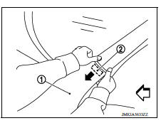
8. Remove front fender.
CAUTION: A viscous urethane foam is installed on the back surface of front fender. When removing the front fender, be careful to not deform the front fender while performing the procedure and removing the viscous urethane foam a little at a time.
INSTALLATION
Installation is in the reverse order of removal.
CAUTION:
- Adjust the following components as necessary.
- Hood assembly: Refer to DLK "HOOD ASSEMBLY : Adjustment".
- Front door assembly: Refer to DLK "DOOR ASSEMBLY : Adjustment".
- After adjusting, apply touch-up paint (body color) onto the head of the front fender bolts.
 Radiator core support lower
RADIATOR CORE SUPPORT LOWER : Removal and Installation RADIATOR CORE SUPPORT LOWER Removal 1. Remove under cover. Refer to EXT "Removal and Installation". 2. Remove radiator upper sea ...
Fender cover
FENDER COVER : Removal and Installation REMOVAL 1. Fully open hood assembly. 2. Disengage pawls beginning at the front of the fender cover and working toward the rear of vehicle and then remove fr ...
Other materials:
Fuel pressure check
Work Procedure
FUEL PRESSURE RELEASE
1.FUEL PRESSURE RELEASE
With CONSULT
Turn ignition switch ON.
Perform "FUEL PRESSURE RELEASE" in "WORK SUPPORT" mode with CONSULT.
Start engine.
After engine stalls, crank it two or three times to release all fuel
pressure.
Turn ignition switc ...
U1000 Can comm circuit
Description
CAN (Controller Area Network) is a serial communication line for real-time
application. It is an on-vehicle multiplex
communication line with high data communication speed and excellent malfunction
detection ability.
Many electronic control units are equipped onto a vehicle, and ...
Categories
- Manuals Home
- Nissan Versa Owners Manual
- Nissan Versa Service Manual
- Video Guides
- Questions & Answers
- External Resources
- Latest Updates
- Most Popular
- Sitemap
- Search the site
- Privacy Policy
- Contact Us

0.0072