Nissan Versa (N17): Fuel level sensor unit, fuel filter and fuel pump assembly
Exploded View
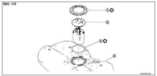
1. Lock ring 2. Fuel level sensor unit, fuel filter and fuel pump assembly 3. O-ring 4. Fuel tank
Removal and Installation
WARNING: Be sure to read "General Precautions" before working on the fuel system. Refer to FL, "General Precautions".
REMOVAL
- Release the fuel pressure from the fuel lines. Refer to EC, "Work Procedure".
- Check fuel level with vehicle on a level surface. If the fuel level is 7/8 of the fuel tank (full or nearly full), draw appropriate amount of fuel from the fuel tank.
Guideline : Draw approximately 10 liters (2-5/8 US gal, 2-1/4 Imp gal) from a full-tank condition.
- In the event of malfunction in fuel pump, insert a hose measuring 20 mm (0.79 in) in diameter into the filler opening to draw approximately 10 liters (2-5/8 US gal, 2-1/4 Imp gal) fuel.
- Open fuel filler lid.
- Open fuel filler cap and release the pressure inside fuel tank.
- Remove the rear seat cushion. Refer to SE, "Removal and Installation - Seat Cushion Assembly".
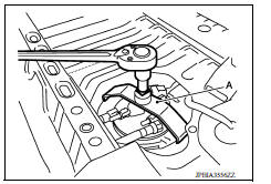
- Remove the inspection hole cover.
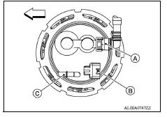
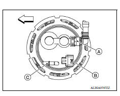
- Disconnect the harness connector (B), fuel feed tube (C) and EVAP tube (A).
 : Front
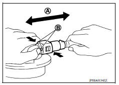
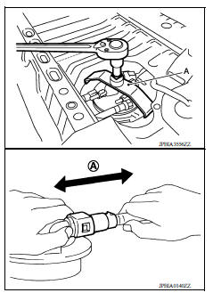
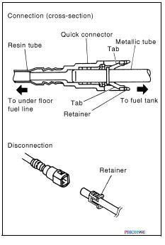
Remove the quick connector as follows:
- Hold the sides of the connector, push in tabs (B) and pull (A) out the tube.
- If the connector and the tube are stuck together, push and pull several times until they start to move. Then disconnect them by pulling.
CAUTION:
- The tube can be removed when the tabs are completely depressed. Do not twist it more than necessary.
- Do not use any tools to remove the quick connector.
- Keep the resin tube away from heat. Be especially careful when welding near the tube.
- Prevent acid liquid such as battery electrolyte, etc. from getting on the resin tube.
- Do not bend or twist the tube during installation and removal.
- Only when the tube is replaced, remove the remaining retainer on the tube or fuel level sensor, fuel filter, and fuel pump assembly.
- When the tube or fuel level sensor, fuel filter, and fuel pump assembly is replaced, also replace the retainer with a new one (green colored retainer).
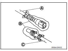
- To keep the connecting portion clean and to avoid damage and foreign materials, cover them completely with plastic bags (B) or something similar.
(A) : Fuel feed hose
(C) : Fuel tube
8. Remove the lock ring using Tool (A).
Tool number : KV10119900 (J-45722)
NOTE: For reference when installing, put a matching mark on lock ring, fuel pump assembly and fuel tank.
9. Remove fuel level sensor unit, fuel filter and fuel pump assembly. Remove and discard the O-ring.
CAUTION:
- Do not bend the float arm during removal.
- Do not reuse O-ring.
INSPECTION AFTER REMOVAL
Inspect the fuel level sensor, fuel filter, and fuel pump assembly for any defects and foreign materials. Replace as necessary.
INSTALLATION
Installation is in the reverse order of removal.
- Install the fuel level sensor, fuel filter, and fuel pump assembly with
the fuel feed tube (C) facing the front of the vehicle as shown. Use
a new O-ring.
CAUTION: Do not reuse O-ring.
 : Front
(A) : EVAP tube
(B) : Harness connector
- Install the lock ring using Tool (A).
Tool number : KV10119900 (J-45722)
NOTE: For reference when installing, align the matching marks on lock ring, fuel pump assembly and fuel tank.
- Connect the quick connector as follows:
- Check the connection for damage or any foreign materials.
- Align the connector with the tube, then insert the connector straight into the tube until a click is heard.
- After the tube is connected, make sure the connection is secure by performing the following checks:
- Pull (A) the tube and the connector to make sure they are securely connected.
- Visually confirm that the two retainer tabs are connected to the quick connector.
 Precautions
Fuel tank
Exploded View 1. Fuel tank 2. Fuel tank mounting band (RH) 3. Fuel tank mounting band (LH) 4. Clamp 5. Fuel filler hose 6. Fuel filler tube 7. Grommet 8. Fuel filler cap 9. Clamp 10. Vent hose ...
Other materials:
Windows
Power windows (if so equipped)
WARNING
Make sure that all passengers have
their hands, etc. inside the vehicle while
it is in motion and before closing the
windows. Use the window lock switch to
prevent unexpected use of the power
windows
To help avoid risk of injury or death
thr ...
RearView Monitor (if so equipped)
1. CAMERA button (models with navigation)
WARNING
Failure to follow the warnings and instructions
for proper use of the Rear-
View Monitor system could result in serious
injury or death.
RearView Monitor is a convenience feature
and is not a substitute for proper
backing. Always ...
Categories
- Manuals Home
- Nissan Versa Owners Manual
- Nissan Versa Service Manual
- Video Guides
- Questions & Answers
- External Resources
- Latest Updates
- Most Popular
- Sitemap
- Search the site
- Privacy Policy
- Contact Us

0.0072