Nissan Versa (N17): Power door lock system
POWER DOOR LOCK SYSTEM : System Diagram
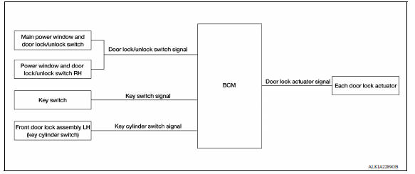
POWER DOOR LOCK SYSTEM : System Description 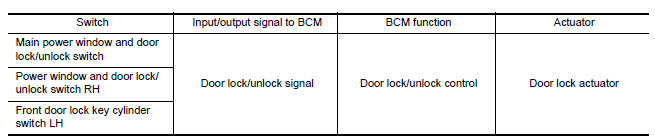
DOOR LOCK FUNCTION
Functions Available by Operating the Door Lock and Unlock Switches on Driver Door and Passenger Door
- Interlocked with the locking operation of door lock and unlock switch, door lock actuators of all door lock actuators are locked.
- Interlocked with the unlocking operation of door lock and unlock switch, door lock actuators of all door lock actuators are unlocked.
Functions Available by Operating the Key Cylinder Switch on Driver Door
- Interlocked with the locking operation of door key cylinder, door lock actuators of all door lock actuators are locked.
Selective Unlock Operation
- When door key cylinder is unlocked, door lock actuator driver side is unlocked.
- When door key cylinder is unlocked for the second time within 5 seconds after the first operation, door lock actuators on all doors are unlocked.
Select unlock operation mode can be changed using DOOR LOCK-UNLOCK SET mode in "WORK SUPPORT".
Refer to BCS "DOOR LOCK : CONSULT Function (BCM - DOOR LOCK)".
 Automatic door lock/unlock function
AUTOMATIC DOOR LOCK/UNLOCK FUNCTION : System Diagram AUTOMATIC DOOR LOCK/UNLOCK FUNCTION : System Description DOOR LOCK FUNCTION The door lock and unlock switch (driver side) is built i ...
Remote keyless entry system
REMOTE KEYLESS ENTRY SYSTEM : System Diagram REMOTE KEYLESS ENTRY SYSTEM : System Description The remote keyless entry system can be locked and unlocked by pressing door lock and unlock ...
Other materials:
Thermostat
Exploded View
1. Radiator hose (lower) 2. Water inlet 3. Rubber ring
4. Thermostat A. To radiator
Removal and Installation
WARNING:
Do not remove the radiator cap when the engine is hot. Serious burns
could occur from highpressure
engine coolant escaping from the radiator. Wrap a thick cl ...
Fuel level sensor unit
Disassembly and Assembly
Fuel Level Sender Unit
1. Harness connectors 2. Level sending unit module 3. Fuel temperature sensor
4. Float arm assembly
Disassembly
NOTE:
Before disassembly, note the proper placement of the wires to the correct
terminals and correct wire routing to
the term ...
Categories
- Manuals Home
- Nissan Versa Owners Manual
- Nissan Versa Service Manual
- Video Guides
- Questions & Answers
- External Resources
- Latest Updates
- Most Popular
- Sitemap
- Search the site
- Privacy Policy
- Contact Us

0.0063