Nissan Versa (N17): Fuel level sensor unit
Disassembly and Assembly
Fuel Level Sender Unit
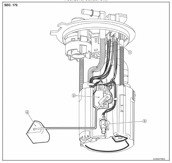
1. Harness connectors 2. Level sending unit module 3. Fuel temperature sensor 4. Float arm assembly
Disassembly
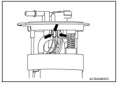
NOTE: Before disassembly, note the proper placement of the wires to the correct terminals and correct wire routing to the terminals.
- Disconnect the red, white, and double black wire connectors.
- Press the tabs on the terminals to release the locking tabs.
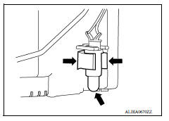
2. Release the two clips and remove the fuel temperature sensor from the pump assembly.
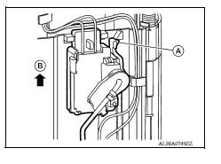
3. Release the tab (A) and slide the level sending unit module and float arm assembly up (B) to remove.
Assembly
Assembly is in the reverse order of disassembly.
NOTE:
- Ensure proper placement of the wires to the correct terminals and correct wire routing to the terminals.
- After connecting terminals, ensure they are securely locked and can not be pulled out.
- When installing the level sending unit, push down until the tab is locked into place.
SERVICE DATA AND SPECIFICATIONS (SDS)
Fuel Tank
STANDARD AND LIMIT
| Fuel tank capacity | Approx. 41.0  (10-7/8 US
gal, 9 Imp gal) (10-7/8 US
gal, 9 Imp gal) |
| Fuel recommendation | Refer to GI, "Fuel (Regular Unleaded Gasoline Recommended) HR16DE". |
 EVAP control system pressure sensor
Exploded View 1. EVAP control system pressure sensor 2. O-ring 3. EVAP canister Removal and Installation NOTE: The EVAP canister system pressure sensor can be removed without removing the E ...
Precautions
Precaution for Supplemental Restraint System (SRS) "AIR BAG" and "SEAT BELT PRE-TENSIONER" The Supplemental Restraint System such as "AIR BAG" and "SEAT BELT PRE-TENSIONER", us ...
Other materials:
B terminal circuit
Description
Terminal "B" is constantly supplied with battery power.
Diagnosis Procedure
Regarding Wiring Diagram information, refer to STR, "Wiring Diagram - With
Intelligent Key System" or
STR, "Wiring Diagram - Without Intelligent Key System".
CAUTION: Perform diagnosis ...
EPS Warning lamp does not turn
OFF
Description
EPS warning lamp does not turn OFF several seconds after engine started.
Diagnosis Procedure
1.PERFORM SELF-DIAGNOSIS
With CONSULT
Turn the ignition switch OFF to ON.
Perform "EPS" self-diagnosis.
Is any DTC detected?
YES >> Check the DTC. Refer to STC "DTC Inde ...
Categories
- Manuals Home
- Nissan Versa Owners Manual
- Nissan Versa Service Manual
- Video Guides
- Questions & Answers
- External Resources
- Latest Updates
- Most Popular
- Sitemap
- Search the site
- Privacy Policy
- Contact Us

0.0053