Nissan Versa (N17): Precautions
Precaution for Supplemental Restraint System (SRS) "AIR BAG" and "SEAT BELT PRETENSIONER"
The Supplemental Restraint System such as "AIR BAG" and "SEAT BELT PRETENSIONER", used along with a front seat belt, helps to reduce the risk or severity of injury to the driver and front passenger for certain types of collision. This system includes seat belt switch inputs and dual stage front air bag modules. The SRS system uses the seat belt switches to determine the front air bag deployment, and may only deploy one front air bag, depending on the severity of a collision and whether the front occupants are belted or unbelted.
Information necessary to service the system safely is included in the SR and SB section of this Service Manual.
WARNING:
- To avoid rendering the SRS inoperative, which could increase the risk of personal injury or death in the event of a collision which would result in air bag inflation, all maintenance must be performed by an authorized NISSAN/INFINITI dealer.
- Improper maintenance, including incorrect removal and installation of the SRS, can lead to personal injury caused by unintentional activation of the system. For removal of Spiral Cable and Air Bag Module, see the SR section.
- Do not use electrical test equipment on any circuit related to the SRS unless instructed to in this Service Manual. SRS wiring harnesses can be identified by yellow and/or orange harnesses or harness connectors.
PRECAUTIONS WHEN USING POWER TOOLS (AIR OR ELECTRIC) AND HAMMERS
WARNING:
- When working near the Airbag Diagnosis Sensor Unit or other Airbag System sensors with the Ignition ON or engine running, DO NOT use air or electric power tools or strike near the sensor(s) with a hammer. Heavy vibration could activate the sensor(s) and deploy the air bag(s), possibly causing serious injury.
- When using air or electric power tools or hammers, always switch the Ignition OFF, disconnect the battery, and wait at least 3 minutes before performing any service.
Precaution for Liquid Gasket
REMOVAL OF LIQUID GASKET
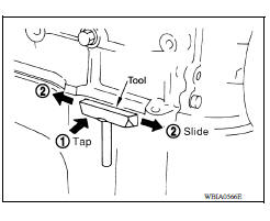
- After removing the bolts and nuts, separate the mating surface and remove the old liquid gasket using Tool.
Tool number : KV10111100 (J37228)
CAUTION:
Do not damage the mating surfaces.
- Tap the seal cutter to insert it (1).
- In areas where the Tool is difficult to use, lightly tap to slide it (2).
LIQUID GASKET APPLICATION PROCEDURE
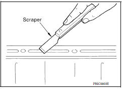
1. Remove the old liquid gasket adhering to the gasket application surface and the mating surface using suitable tool.
- Remove the liquid gasket completely from the groove of the liquid gasket application surface, bolts, and bolt holes.
2. Thoroughly clean the mating surfaces and remove adhering moisture, grease and foreign material.
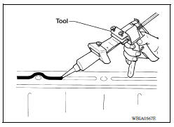
3. Attach the liquid gasket tube to the Tool.
Tool number : WS39930000 ( - )
Use Genuine RTV Silicone Sealant or equivalent.
4. Apply the liquid gasket without breaks to the specified location with the specified dimensions.
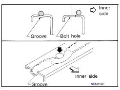
- If there is a groove for the liquid gasket application, apply the liquid gasket to the groove.
- Normally apply the liquid gasket on the inside edge of the bolt holes. Also apply to the outside edge of the bolt holes when specified in the procedure.
- Within five minutes of liquid gasket application, install the mating component.
- If the liquid gasket protrudes, wipe it off immediately.
- Do not retighten after the installation.
- Wait 30 minutes or more after installation before refilling the engine with oil or coolant.
CAUTION:
If there are more specific instructions in the procedures contained in this manual concerning liquid gasket application, observe them.
 Service data and specifications
(sds)
Service data and specifications
(sds)
General Specification GENERAL SPECIFICATIONS Engine type HR16DE Cylinder arrangement Inline 4 Displacement ...
Preparation
Special Service Tools The actual shapes of KentMoore tools may differ from those of special service tools illustrated here. Tool number (KentMoore No.) Tool name Description ...
Other materials:
Sensor rotor
FRONT SENSOR ROTOR
FRONT SENSOR ROTOR : Removal and Installation
REMOVAL
The front wheel sensor rotor is an integral part of the wheel hub and bearing
assembly and can not be
replaced individually. When replacing the front wheel sensor rotor replace the
hub and bearing assembly.
Refer to ...
Power supply and ground circuit
Diagnosis Procedure
Regarding Wiring Diagram information, refer to BCS "Wiring Diagram".
1.CHECK FUSES AND FUSIBLE LINK
Check that the following fuses and fusible link are not blown.
Is the fuse blown?
YES >> Replace the blown fuse or fusible link after repairing the a ...
Categories
- Manuals Home
- Nissan Versa Owners Manual
- Nissan Versa Service Manual
- Video Guides
- Questions & Answers
- External Resources
- Latest Updates
- Most Popular
- Sitemap
- Search the site
- Privacy Policy
- Contact Us

0.0103