Nissan Versa (N17): Precautions
Precaution for Supplemental Restraint System (SRS) "AIR BAG" and "Seat belt pre-tensioner"
The Supplemental Restraint System such as "AIR BAG" and "SEAT BELT PRE-TENSIONER", used along with a front seat belt, helps to reduce the risk or severity of injury to the driver and front passenger for certain types of collision. This system includes seat belt switch inputs and dual stage front air bag modules. The SRS system uses the seat belt switches to determine the front air bag deployment, and may only deploy one front air bag, depending on the severity of a collision and whether the front occupants are belted or unbelted.
Information necessary to service the system safely is included in the SR and SB section of this Service Manual.
WARNING:
- To avoid rendering the SRS inoperative, which could increase the risk of personal injury or death in the event of a collision which would result in air bag inflation, all maintenance must be performed by an authorized NISSAN/INFINITI dealer.
- Improper maintenance, including incorrect removal and installation of the SRS, can lead to personal injury caused by unintentional activation of the system. For removal of Spiral Cable and Air Bag Module, see the SR section.
- Do not use electrical test equipment on any circuit related to the SRS unless instructed to in this Service Manual. SRS wiring harnesses can be identified by yellow and/or orange harnesses or harness connectors.
PRECAUTIONS WHEN USING POWER TOOLS (AIR OR ELECTRIC) AND HAMMERS
WARNING:
- When working near the Airbag Diagnosis Sensor Unit or other Airbag System sensors with the Ignition ON or engine running, DO NOT use air or electric power tools or strike near the sensor(s) with a hammer. Heavy vibration could activate the sensor(s) and deploy the air bag(s), possibly causing serious injury.
- When using air or electric power tools or hammers, always switch the Ignition OFF, disconnect the battery, and wait at least 3 minutes before performing any service.
Precaution for Work
- When removing or disassembling each component, be careful not to damage or deform it. If a component may be subject to interference, be sure to protect it with a shop cloth.
- When removing (disengaging) components with a screwdriver or similar tool, be sure to wrap the component with a shop cloth or vinyl tape to protect it.
- Protect the removed parts with a shop cloth and prevent them from being dropped.
- Replace a deformed or damaged clip.
- If a part is specified as a non-reusable part, always replace it with a new one.
- Be sure to tighten bolts and nuts securely to the specified torque.
- After installation is complete, be sure to check that each part works properly.
- Follow the steps below to clean components:
- Water soluble dirt:
- Dip a soft cloth into lukewarm water, wring the water out of the cloth and wipe the dirty area.
- Then rub with a soft, dry cloth.
- Oily dirt:
- Dip a soft cloth into lukewarm water with mild detergent (concentration: within 2 to 3%) and wipe the dirty area.
- Then dip a cloth into fresh water, wring the water out of the cloth and wipe the detergent off.
- Then rub with a soft, dry cloth.
- Do not use organic solvent such as thinner, benzene, alcohol or gasoline.
- For genuine leather seats, use a genuine leather seat cleaner.
General Precautions
- Turn the ignition switch OFF and disconnect the battery cable from the negative terminal before connecting or disconnecting the A/T assembly harness connector. Because battery voltage is applied to TCM even if ignition switch is turned OFF.
- When connecting or disconnecting pin connectors into or
from TCM, do not damage pin terminals (bend or break).
Check that there are not any bends or breaks on TCM pin terminal, when connecting pin connectors.
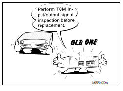
- Perform TCM input/output signal inspection and check
whether TCM functions normally or not before replacing TCM.
Refer to TM, "Reference Value".
- Perform "DTC (Diagnostic Trouble Code) CONFIRMATION
PROCEDURE".
If the repair is completed DTC should not be displayed in the "DTC CONFIRMATION PROCEDURE".
- Always use the specified brand of ATF. Refer to MA, "Fluids and Lubricants".
- Use lint-free paper not cloth rags during work.
- Dispose of the waste oil using the methods prescribed by law, ordinance, etc. after replacing the ATF.
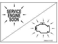
On Board Diagnosis (OBD) System of A/T and Engine
The ECM has an on board diagnostic system. It will light up the malfunction indicator (MI) to warn the driver of a malfunction causing emission deterioration.
CAUTION:
- Be sure to turn the ignition switch OFF and disconnect the battery cable from the negative terminal before any repair or inspection work. The open/short circuit of related switches, sensors, solenoid valves, etc. will cause the MI to light up.
- Be sure to connect and lock the connectors securely after work. A loose (unlocked) connector will cause the MI to light up due to an open circuit. (Be sure the connector is free from water, grease, dirt, bent terminals, etc.)
- Be sure to route and secure the harnesses properly after work. Interference of the harness with a bracket, etc. may cause the MI to light up due to a short circuit.
- Be sure to connect rubber tubes properly after work. A misconnected or disconnected rubber tube may cause the MI to light up due to a malfunction of the EGR system or fuel injection system, etc.
- Be sure to erase the unnecessary malfunction information (repairs completed) from the TCM and ECM before returning the vehicle to the customer.
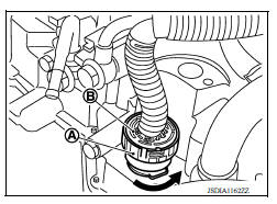
Removal and Installation Procedure for A/T Assembly Connector
REMOVAL
Rotate bayonet ring (A) counterclockwise. Pull out A/T assembly harness connector (B) upward and remove it.
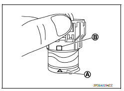
INSTALLATION
1. Align marking (A) on A/T assembly harness connector terminal body with marking (B) on bayonet ring. Insert A/T assembly harness connector. Then rotate bayonet ring clockwise.
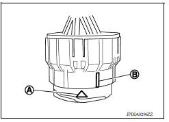
2. Rotate bayonet ring clockwise until marking (A) on A/T assembly harness connector terminal body is aligned with the slit (B) on bayonet ring as shown in the figure (correctly fitting condition).
Install A/T assembly harness connector to A/T assembly harness connector terminal body.
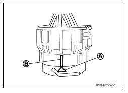
CAUTION:
- Securely align marking (A) on A/T assembly harness connector terminal body with bayonet ring slit (B). Then, be careful not to make a half fit condition as shown in the figure.
- Do not mistake the slit of bayonet ring for other dent portion.
Service Notice or Precaution
OBD SELF-DIAGNOSIS
- A/T self-diagnosis is performed by the TCM in combination with the ECM. The results can be read through the blinking pattern of the A/T CHECK indicator or the malfunction indicator Lamp (MIL). Refer to the table on "SELF-DIAGNOSTIC RESULTS" for the indicator used to display each self-diagnostic result. Refer to TM, "CONSULT Function".
- The self-diagnostic results indicated by the MI are automatically stored
in both the ECM and TCM memories.
Always perform the procedure on "How to Erase DTC" to complete the repair and avoid unnecessary blinking of the MI. Refer to TM, "Description".
For details of OBD, refer to TM, "DIAGNOSIS DESCRIPTION : 1 Trip Detection Diagnosis and 2 Trip Detection Diagnosis".
- Certain systems and components, especially those related to OBD, may use the new style slide-locking type harness connector. For description and how to disconnect, refer to GI, "Description".
Preparation
Special service tools
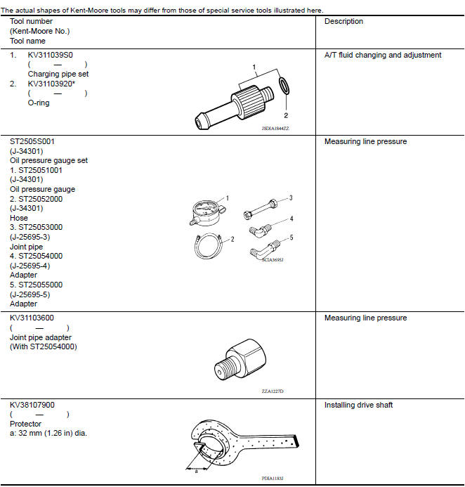
*: The O-ring is a unit part and is set as a SST.
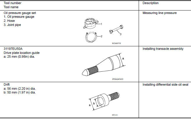
Commercial service tools
 Final drive
Exploded View 1. Differential side bearing outer race 2. Differential side bearing 3. Final drive : Replace the parts as a set. Disassembly Remove differential side bearings, using Tool ...
A/T Control system
A/T Control system : component parts location 1. IPDM E/R 2. TCM 3. Transmission range switch 4. A/T unit 5. Output speed sensor 6. Stop lamp switch 7. A/T shift selector 8. Overdrive control s ...
Other materials:
Precautions
Precaution for Supplemental Restraint System
(SRS) "AIR BAG" and "SEAT BELT PRE-TENSIONER"
The Supplemental Restraint System such as "AIR BAG" and "SEAT BELT PRE-TENSIONER",
used along
with a front seat belt, helps to reduce the risk or severity of injury to the
driver and ...
STRG Branch line circuit
Diagnosis Procedure
1.CHECK CONNECTOR
1. Turn the ignition switch OFF.
2. Disconnect the battery cable from the negative terminal.
3. Check the terminals and connectors of the steering angle sensor for
damage, bend and loose connection
(unit side and connector side).
Is the inspection result ...
Categories
- Manuals Home
- Nissan Versa Owners Manual
- Nissan Versa Service Manual
- Video Guides
- Questions & Answers
- External Resources
- Latest Updates
- Most Popular
- Sitemap
- Search the site
- Privacy Policy
- Contact Us

0.0069