Nissan Versa (N17): Wheel alignment
Inspection
DESCRIPTION
CAUTION:
- The adjustment mechanisms of camber and toe-in are not included.
- If camber and toe-in is outside the standard, check front
suspension parts for wear and damage.
Replace suspect parts if a malfunction is detected.
Measure wheel alignment under unladen conditions.
NOTE: "Unladen conditions" means that fuel, engine coolant, and lubricant are full. Spare tire, jack, hand tools and mats are in designated positions.
PRELIMINARY CHECK
Check the following:
- Tires for improper air pressure and wear. Refer to WT "Tire Air Pressure".
- Road wheels for runout.
- Wheel bearing axial end play. Refer to RAX "Inspection".
- Shock absorber operation.
- Each mounting point of axle and suspension for looseness and deformation.
- Each of rear suspension beam and shock absorber for cracks, deformation, and other damage.
- Vehicle height (posture).
GENERAL INFORMATION AND RECOMMENDATIONS
1. A Four-Wheel Thrust Alignment should be performed.
- This type of alignment is recommended for any NISSAN vehicle.
- The four-wheel "thrust" process helps ensure that the vehicle is properly aligned and the steering wheel is centered.
- The alignment machine itself should be capable of accepting any NISSAN vehicle.
- The alignment machine should be checked to ensure that it is level.
2. Make sure the alignment machine is properly calibrated.
- Your alignment machine should be regularly calibrated in order to give correct information.
- Check with the manufacturer of your specific alignment machine for their recommended Service/Calibration Schedule.
THE ALIGNMENT PROCESS
IMPORTANT:
Use only the alignment specifications listed in this Service Manual.
- When displaying the alignment settings, many alignment machines use "indicators" Do not use these indicators.: (Green/red, plus or minus, Go/No Go).
- The alignment specifications programmed into your machine that operate these indicators may not be correct.
- This may result in an ERROR.
- Most camera-type alignment machines are equipped with both "Rolling Compensation" method and optional "Jacking Compensation" method to "compensate" the alignment targets or head units. "Rolling Compensation" is the preferred method.
- If using the "Rolling Compensation" method, after installing the alignment targets or head units, push or pull on the rear wheel to move the vehicle. Do not push or pull the vehicle body.
- If using the "Jacking Compensation" method, after installing the alignment targets or head units, raise the vehicle and rotate the wheels 1/2 turn both ways.
NOTE: Do not use the "Rolling Compensation" method if you are using sensor-type alignment equipment.
- Follow all instructions for the alignment machine you're using for more information.
CAMBER
- Measure camber of both right and left wheels with a suitable alignment gauge.
- If camber is outside specified range, replace rear suspension beam. Refer to RSU "Exploded View".
Camber : Refer to RSU "Wheel Alignment".
TOE-IN
Measure toe-in by the following procedure.
WARNING:
- Always perform the following procedure on a flat surface.
- Check that no person is in front of vehicle before pushing it.
- Bounce the front of vehicle up and down to stabilize the vehicle height (posture).
- Push vehicle straight ahead about 5 m (16 ft).
- Put matching mark (A) on base line of the tread (rear side) of both tires at the same height of hub center. These are measuring points.
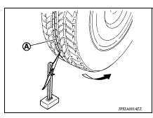
4. Measure distance (A) (rear side).
 : Front
5. Push vehicle slowly ahead to rotate wheels 180 degrees (1/2 turn).
NOTE: If the wheels rotates more than 180 degrees (1/2 turn), start this procedure again from the beginning. Do not push the vehicle backward.
6. Measure distance (B) (front side).
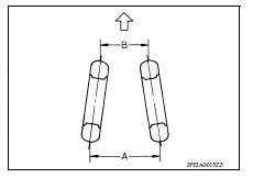
Total toe-in = A − B
Total toe-in : Refer to RSU "Wheel Alignment".
- If toe-in is outside specified range, replace rear suspension beam. Refer to RSU "Exploded View".
REMOVAL AND INSTALLATION
 Precautions
Precaution for Supplemental Restraint System (SRS) "AIR BAG" and "SEAT BELT PRE-TENSIONER" The Supplemental Restraint System such as "AIR BAG" and "SEAT BELT PRE-TENSIONER", us ...
Rear shock absorber
Exploded View 1. Piston rod lock nut 2. Washer 3. Bushing 4. Distance tube 5. Bound bumper cover 6. Bound bumper 7. Shock absorber assembly 8. Rear suspension beam ...
Other materials:
Hazard warning flasher switch
Push the switch on to warn other drivers when
you must stop or park under emergency conditions.
All turn signal lights flash.
WARNING
If stopping for an emergency, be sure to
move the vehicle well off the road.
Do not use the hazard warning flashers
while moving on the highway unl ...
Insufficient cooling
Description
Symptom
Insufficient cooling
No cool air comes out. (Air flow volume is normal.)
Diagnosis Procedure
NOTE:
Perform self-diagnosis with CONSULT before performing symptom diagnosis. If any
malfunction result or DTC
is detected, perform the corresponding diagnosis.
1.CHE ...
Categories
- Manuals Home
- Nissan Versa Owners Manual
- Nissan Versa Service Manual
- Video Guides
- Questions & Answers
- External Resources
- Latest Updates
- Most Popular
- Sitemap
- Search the site
- Privacy Policy
- Contact Us

0.0056