Nissan Versa (N17): ABS Actuator and electric unit (control unit)
Exploded View
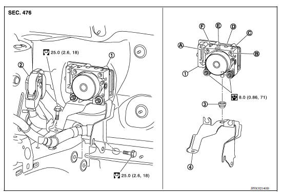
1. ABS actuator and electric unit (control unit) 2. ABS actuator and electric unit (control unit) harness connector 3. Bushing 4. Bracket A. To master cylinder secondary side B. To master cylinder primary side C. To front wheel cylinder (LH) D. To rear wheel cylinder (RH) E. To rear wheel cylinder (LH) F. To front wheel cylinder (RH)
Removal and Installation
CAUTION:
Be careful of the following:
- Before servicing, disconnect the battery cable from negative terminal.
- To remove brake tubes, use a suitable tool (flare nut wrench) to prevent flare nuts and brake tubes from being damaged. To install, use suitable tool (flare nut torque wrench).
- Do not apply excessive impact to ABS actuator and electric unit (control unit), such as by dropping it.
- Do not remove and install ABS actuator and electric unit (control unit) by holding harness.
- After work is completed, bleed air from brake tubes. Refer to BR "Bleeding Brake System".
- After installing harness connector on the ABS actuator and electric unit (control unit), make sure connector is securely locked.
NOTE: When removing components such as hoses, tubes/lines, etc., cap or plug openings to prevent fluid from spilling.
REMOVAL
- Disconnect battery cable from negative terminal. Refer to PG "Removal and Installation".
- Remove A/C high-pressure pipe. Refer to HA "Removal and Installation".
- Remove A/C low-pressure flexible hose. Refer to HA "Removal and Installation".
- Disconnect the harness connector from the ABS actuator and electric unit (control unit).
- Loosen flare nut of brake tube using a flare nut wrench, and then remove brake tube from ABS actuator and electric unit (control unit). Refer to BRC "Exploded View".
- Remove ABS actuator and electric unit (control unit) and bracket.
- Remove bracket and bushing from ABS actuator and electric unit (control unit), if necessary.
INSTALLATION
Installation is in the reverse order of removal.
- Bleed the brake system. Refer to BR "Bleeding Brake System".
CAUTION: If ABS actuator and electronic unit (control unit) is replaced, after installation, adjust position of steering angle sensor. Refer to BRC "Work Procedure".
VDC OFF SWITCH
Removal and Installation
REMOVAL
- Remove the instrument lower panel LH. Refer to IP "Exploded View".
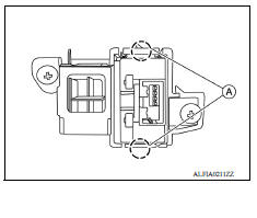
- Release pawls (A) using suitable tool and remove the VDC OFF switch.
INSTALLATION
Installation is in the reverse order of removal.
STEERING ANGLE SENSOR
Removal and Installation
REMOVAL
- Remove the spiral cable. Refer to SR "Removal and Installation".
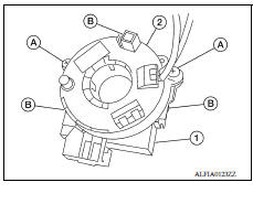
- Remove the screws (A) and release the clips (B) then remove the steering angle sensor (1) from the spiral cable (2).
INSTALLATION
Installation is in the reverse order of removal.
Reset the neutral position of the steering angle sensor. Refer to BRC "Work Procedure".
CAUTION: Any time the steering angle sensor is removed and installed or replaced, the neutral position of the steering angle sensor must be reset.
 Sensor rotor
FRONT SENSOR ROTOR FRONT SENSOR ROTOR : Removal and Installation REMOVAL The front wheel sensor rotor is an integral part of the wheel hub and bearing assembly and can not be replaced individual ...

Other materials:
A/T Control system
A/T Control system : component parts location
1. IPDM E/R 2. TCM 3. Transmission range switch
4. A/T unit 5. Output speed sensor 6. Stop lamp switch
7. A/T shift selector 8. Overdrive control switch 9. Combination meter (type B)
A/T Control system : component description
Name
...
P2857 Clutch A pressure
DTC Logic
DTC DETECTION LOGIC
DTC
Trouble diagnosis name
DTC detection condition
Possible causes
P2857
Clutch A pressure engagement
performance
The auxiliary gearbox gear ratio is 2.232 or
more for the auxiliary gearbox 1GR ratio continuously
for 5 seconds o ...
Categories
- Manuals Home
- Nissan Versa Owners Manual
- Nissan Versa Service Manual
- Video Guides
- Questions & Answers
- External Resources
- Latest Updates
- Most Popular
- Sitemap
- Search the site
- Privacy Policy
- Contact Us

0.0091