Nissan Versa (N17): ABS Branch line circuit
Diagnosis Procedure
1.CHECK CONNECTOR
1. Turn the ignition switch OFF.
2. Disconnect the battery cable from the negative terminal.
3. Check the terminals and connectors of the ABS actuator and electric unit (control unit) for damage, bend and loose connection (unit side and connector side).
Is the inspection result normal?
YES >> GO TO 2.
NO >> Repair the terminal and connector.
2.CHECK HARNESS FOR OPEN CIRCUIT
1. Disconnect the connector of ABS actuator and electric unit (control unit).
2. Check the resistance between the ABS actuator and electric unit (control
unit) harness connector terminals.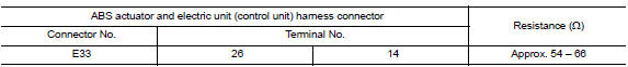
Is the measurement value within the specification?
YES >> GO TO 3.
NO >> Repair the ABS actuator and electric unit (control unit) branch line.
3.CHECK POWER SUPPLY AND GROUND CIRCUIT
Check the power supply and the ground circuit of the ABS actuator and electric unit (control unit). Refer to BRC "Diagnosis Procedure".
Is the inspection result normal?
YES (Present error)>>Replace the ABS actuator and electric unit (control unit). Refer to BRC "Removal and Installation".
YES (Past error)>>Error was detected in the ABS actuator and electric unit (control unit) branch line.
NO >> Repair the power supply and the ground circuit.
 ECM Branch line circuit
Diagnosis Procedure 1.CHECK CONNECTOR 1. Turn the ignition switch OFF. 2. Disconnect the battery cable from the negative terminal. 3. Check the terminals and connectors of the ECM for damage, be ...
IPDM-E Branch line circuit
Diagnosis Procedure 1.CHECK CONNECTOR 1. Turn the ignition switch OFF. 2. Disconnect the battery cable from the negative terminal. 3. Check the terminals and connectors of the IPDM E/R for damage, ...
Other materials:
Fuel injector and fuel tube
Exploded View
1. Stud bolt 2. Oring (green) 3. Fuel injector (front) 4. Clip 5. Fuel
injector (rear) 6. Oring (black) 7. Fuel tube protector 8. Fuel tube 9. Clamp
10. Quick connector cap (engine side) 11. Fuel feed hose 12. Quick connector cap
(floor pipingside) 13. Fuel connector protect ...
Mixture ratio selflearning value
clear
Description
This describes how to erase the mixture ratio selflearning value. For the
actual procedure, follow the instructions
in "Diagnosis Procedure".
Work Procedure
1.START
With CONSULT
Start engine and warm it up to normal operating temperature.
Select "SELFLEARNING CONT" in "WOR ...
Categories
- Manuals Home
- Nissan Versa Owners Manual
- Nissan Versa Service Manual
- Video Guides
- Questions & Answers
- External Resources
- Latest Updates
- Most Popular
- Sitemap
- Search the site
- Privacy Policy
- Contact Us

0.0051