Nissan Versa (N17): ECM Branch line circuit
Diagnosis Procedure
1.CHECK CONNECTOR
1. Turn the ignition switch OFF.
2. Disconnect the battery cable from the negative terminal.
3. Check the terminals and connectors of the ECM for damage, bend and loose connection (unit side and connector side).
Is the inspection result normal?
YES >> GO TO 2.
NO >> Repair the terminal and connector.
2.CHECK HARNESS FOR OPEN CIRCUIT
1. Disconnect the connector of ECM.
2. Check the resistance between the ECM harness connector terminals.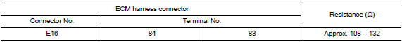
Is the measurement value within the specification?
YES >> GO TO 3.
NO >> Repair the ECM branch line.
3.CHECK POWER SUPPLY AND GROUND CIRCUIT
Check the power supply and the ground circuit of the ECM. Refer to EC "Diagnosis Procedure".
Is the inspection result normal?
YES (Present error)>>Replace the ECM. Refer to EC "Removal and Installation".
YES (Past error)>>Error was detected in the ECM branch line.
NO >> Repair the power supply and the ground circuit.
 Main line between IPDM-E and DLC
circuit
Main line between IPDM-E and DLC
circuit
Diagnosis Procedure 1.CHECK CONNECTOR 1. Turn the ignition switch OFF. 2. Disconnect the battery cable from the negative terminal. 3. Check the following terminals and connectors for damage, bend ...
ABS Branch line circuit
Diagnosis Procedure 1.CHECK CONNECTOR 1. Turn the ignition switch OFF. 2. Disconnect the battery cable from the negative terminal. 3. Check the terminals and connectors of the ABS actuator and ele ...
Other materials:
Cold weather driving
Freeing a frozen door lock
To prevent a door lock from freezing, apply deicer
through the key hole. If the lock becomes
frozen, heat the key before inserting it into the key
hole, or use the remote keyless entry key fob or
the NISSAN Intelligent Key.
Antifreeze
In the winter when it is antic ...
Reporting safety defects
For USA
If you believe that your vehicle has a defect
which could cause a crash or could
cause injury or death, you should immediately
inform the National Highway Traffic
Safety Administration (NHTSA) in addition
to notifying NISSAN.
If NHTSA receives similar complaints, it
may open an inv ...
Categories
- Manuals Home
- Nissan Versa Owners Manual
- Nissan Versa Service Manual
- Video Guides
- Questions & Answers
- External Resources
- Latest Updates
- Most Popular
- Sitemap
- Search the site
- Privacy Policy
- Contact Us

0.0047