Nissan Versa (N17): Power supply and ground circuit
Audio unit
AUDIO UNIT : Diagnosis Procedure
Regarding Wiring Diagram information, refer to AV "Wiring Diagram".
1.CHECK FUSE
Check that the following fuses are not blown. 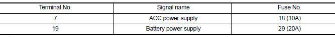
Are the fuses blown?
YES >> Replace the blown fuse after repairing the affected circuit.
NO >> GO TO 2.
2.CHECK POWER SUPPLY CIRCUIT
1. Turn ignition switch OFF.
2. Disconnect audio unit connector M46.
3. Check voltage between audio unit connector M46 and ground.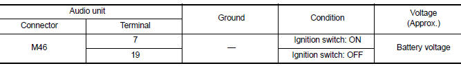
Is the inspection result normal?
YES >> GO TO 3.
NO >> Repair or replace harness or connectors.
3.CHECK GROUND CIRCUIT
1. Turn ignition switch OFF.
2. Disconnect audio unit connector M47.
3. Check continuity between audio unit connectors and ground.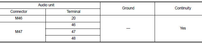
Is the inspection result normal?
YES >> Inspection End.
NO >> Repair or replace harness or connectors.
Bluetooth control unit
BLUETOOTH CONTROL UNIT : Diagnosis Procedure
Regarding Wiring Diagram information, refer to AV "Wiring Diagram".
1.CHECK FUSE
Check that the following fuses are not blown. 
Are the fuses blown?
YES >> Replace the blown fuse after repairing the affected circuit.
NO >> GO TO 2.
2.CHECK POWER SUPPLY CIRCUIT
1. Turn ignition switch OFF.
2. Disconnect Bluetooth control unit connector B33.
3. Check voltage between Bluetooth control unit connector B33 and ground.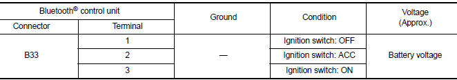
Is the inspection result normal?
YES >> GO TO 3.
NO >> Repair or replace harness or connectors.
3.CHECK GROUND CIRCUIT
1. Turn ignition switch OFF.
2. Check continuity between Bluetooth control unit connector B33 and ground.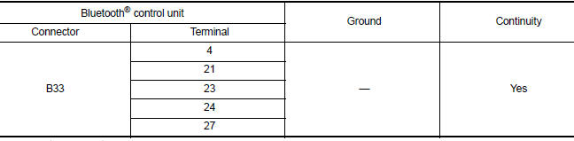
Is the inspection result normal?
YES >> Inspection End.
NO >> Repair or replace harness or connectors.
 Diagnosis and repair workflow
Work Flow OVERALL SEQUENCE DETAILED FLOW 1.GET INFORMATION FOR SYMPTOM Get detailed information from the customer about the symptom (the condition and the environment when the incident/ma ...
Front door speaker
Diagnosis Procedure Regarding Wiring Diagram information, refer to AV "Wiring Diagram". 1.CONNECTOR CHECK Check the audio unit and speaker connectors for the following: Proper connect ...
Other materials:
Oil pan (upper) and oil strainer
Exploded View
1. Rear oil seal 2. Oring 3. Oil pan (upper)
4. Oil pump chain tensioner (for oil
pump drive chain)
5. Oil pump drive chain 6. Crankshaft key
7. Crankshaft sprocket 8. Oil pump sprocket 9. Oil pump
10. Oring 11. Oring 12. Oil pan drain plug
13. Drain plug washer 14. Oil pan ...
Consult function
APPLICATION ITEMS
Diagnostic test mode
Function
Work Support
This mode enables a technician to adjust some devices faster and
more accurately.
Self Diagnostic Results
Retrieve DTC from ECU and display diagnostic items.
Data Monitor
Monitor the input ...
Categories
- Manuals Home
- Nissan Versa Owners Manual
- Nissan Versa Service Manual
- Video Guides
- Questions & Answers
- External Resources
- Latest Updates
- Most Popular
- Sitemap
- Search the site
- Privacy Policy
- Contact Us

0.0093