Nissan Versa (N17): B2267 Engine speed
Description
The engine speed signal is transmitted from ECM to the combination meter via CAN communication.
DTC Logic
DTC DETECTION LOGIC 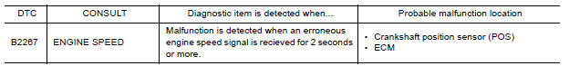
Diagnosis Procedure
1.CHECK COMBINATION METER INPUT SIGNAL
1. Start engine and select METER/M&A on CONSULT.
2. Using TACHO METER on DATA MONITOR, compare the value of DATA MONITOR with tachometer of combination meter. Tachometer and DATA MONITOR indications should be close.
Is the inspection result normal?
YES >> Perform ECM self-diagnosis. Refer to EC"CONSULT Function".
NO >> Replace combination meter. Refer to MWI "Removal and Installation".
B2268 WATER TEMP
Description
The engine coolant temperature signal is transmitted from ECM to the combination meter via CAN communication.
DTC Logic
DTC DETECTION LOGIC 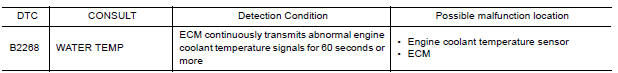
Diagnosis Procedure
1.PERFORM SELF-DIAGNOSIS OF ECM
Perform "Self Diagnosis Result" of "ENGINE", and repair or replace malfunctioning parts.
>> Refer to EC "CONSULT Function".
 DTC B2205 Vehicle speed circuit
Description The ABS actuator and electric unit (control unit) provides a vehicle speed signal to the combination meter via CAN communication lines. DTC Logic ...

Other materials:
Precautions when starting and driving
WARNING
Do not leave children or adults who
would normally require the assistance
of others alone in your vehicle. Pets
should also not be left alone. They
could accidentally injure themselves or
others through inadvertent operation of
the vehicle. Also, on hot, sunny days,
tempera ...
P072C Stuck in 1GR
DTC Logic
DTC DETECTION LOGIC
DTC
Trouble diagnosis name
DTC detection condition
Possible causes
P072C
Stuck in Gear 1
The following diagnosis conditions
are met and the detection
conditions continue for 0.5 seconds
or more.- Diagnosis condition
- Shifti ...
Categories
- Manuals Home
- Nissan Versa Owners Manual
- Nissan Versa Service Manual
- Video Guides
- Questions & Answers
- External Resources
- Latest Updates
- Most Popular
- Sitemap
- Search the site
- Privacy Policy
- Contact Us

0.0056