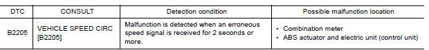
Nissan Versa (N17): DTC B2205 Vehicle speed circuit
Description
The ABS actuator and electric unit (control unit) provides a vehicle speed signal to the combination meter via CAN communication lines.
DTC Logic
Diagnosis Procedure
1.CHECK COMBINATION METER INPUT SIGNAL
1. Start engine and select METER/M&A on CONSULT.
2. Using SPEED METER on DATA MONITOR, compare the DATA MONITOR value with the combination meter speedometer. Speedometer and DATA MONITOR indications should be close.
Is the inspection result normal?
YES >> Perform ABS actuator and electric unit (control unit) self-diagnosis. Refer to BRC "CONSULT Function (ABS)".
NO >> Replace combination meter. Refer to MWI "Removal and Installation".
 U1000 CAN Comm circuit
DTC Logic DTC DETECTION LOGIC Diagn ...
B2267 Engine speed
Description The engine speed signal is transmitted from ECM to the combination meter via CAN communication. DTC Logic DTC DETECTION LOGIC &n ...
Other materials:
Wiper and washer switch
Switch operation
Type A (if so equipped)
The windshield wiper and washer operates when
the ignition switch is in the ON position.
Push the lever down to operate the wiper at the
following speed:
Intermittent (INT) - intermittent operation
can be adjusted by turning the knob toward
...
Fuel-filler door
Opener operation
The fuel-filler door release is located below the
instrument panel. To open the fuel-filler door, pull
the release. To lock, close the fuel-filler door
securely.
Fuel-filler cap
WARNING
Gasoline is extremely flammable and
highly explosive under certain conditions.
...
Categories
- Manuals Home
- Nissan Versa Owners Manual
- Nissan Versa Service Manual
- Video Guides
- Questions & Answers
- External Resources
- Latest Updates
- Most Popular
- Sitemap
- Search the site
- Privacy Policy
- Contact Us

0.0051