Nissan Versa (N17): B261A Push-button ignition switch
DTC Logic
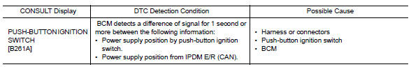
DTC DETECTION LOGIC
DTC CONFIRMATION PROCEDURE
1. PERFORM SELF DIAGNOSTIC RESULT
1. Press the push-button ignition switch under the following conditions, and wait for at least 1 second.
- CVT selector lever is in the P (park) or N (neutral) position.
- Release the brake pedal.
2. Perform self diagnostic result.
Is DTC B261A detected?
YES >> Refer to PCS "Diagnosis Procedure".
NO >> Inspection End.
Diagnosis Procedure
Regarding Wiring Diagram information, refer to PCS "Wiring Diagram".
1. CHECK PUSH-BUTTON IGNITION SWITCH OUTPUT SIGNAL (PUSH-BUTTON IGNITION SWITCH)
1. Disconnect push-button ignition switch connector.
2. Check voltage between push-button ignition switch connector M25 terminal 8
and ground.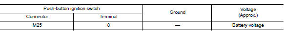
Is the inspection result normal?
YES >> GO TO 2.
NO >> GO TO 4.
2. CHECK IGNITION SWITCH OUTPUT SIGNAL (IPDM E/R)
Check voltage between IPDM E/R connector E47 terminal 81 and ground.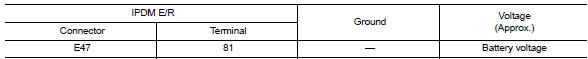
Is the inspection result normal?
YES >> GO TO 3.
NO >> Replace IPDM E/R. Refer to PCS "Removal and Installation".
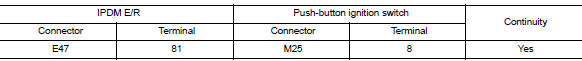
3. CHECK PUSH-BUTTON IGNITION SWITCH CIRCUIT (IPDM E/R)
1. Turn ignition switch OFF.
2. Disconnect IPDM E/R connector E47 and BCM connector M98.
3. Check continuity between IPDM E/R connector E47 terminal 81 and
push-button ignition switch connector
M25 terminal 8.
4. Check continuity between IPDM E/R connector E63 terminal 38 and ground.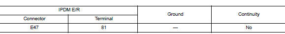
Is the inspection result normal?
YES >> Refer to GI "Intermittent Incident".
NO >> Repair or replace harness or connectors.
4. CHECK IGNITION SWITCH OUTPUT SIGNAL (BCM)
Check voltage between BCM connector M98 terminal 76 and ground.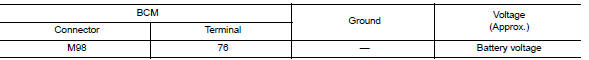
Is the inspection result normal?
YES >> GO TO 5.
NO >> Replace BCM. Refer to BCS "Removal and Installation".
5. CHECK PUSH-BUTTON IGNITION SWITCH CIRCUIT (BCM)
1. Turn ignition switch OFF.
2. Disconnect BCM connector M98 and IPDM E/R connector E47.
3. Check continuity between BCM connector M98 terminal 76 and push-button
ignition switch connector
M25 terminal 8.
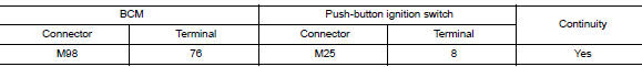
4. Check continuity between BCM connector M98 terminal 76 and ground.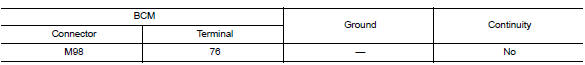
Is the inspection result normal?
YES >> Refer to GI"Intermittent Incident".
NO >> Repair or replace harness or connectors.
 B2618 BCM
Other materials:
Event Data Recorders (EDR)
This vehicle is equipped with an Event Data Recorder
(EDR). The main purpose of an EDR is to
record, in certain crash or near crash-like situations,
such as an air bag deployment or hitting a
road obstacle, data that will assist in understanding
how a vehicle's systems performed. The EDR
is de ...
Air breather hose
Exploded View
1. Cap 2. Air breather hose 3. 2-way connector
Removal and Installation
REMOVAL
Remove air cleaner case. Refer to EM, "Removal and Installation".
Remove air breather hose from the 2-way connector.
CAUTION:
When removing air breather hose, be sure to hold 2- ...
Categories
- Manuals Home
- Nissan Versa Owners Manual
- Nissan Versa Service Manual
- Video Guides
- Questions & Answers
- External Resources
- Latest Updates
- Most Popular
- Sitemap
- Search the site
- Privacy Policy
- Contact Us

0.0055