Nissan Versa (N17): B26F1 Ignition relay
DTC Logic
DTC DETECTION LOGIC
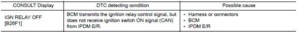
DTC CONFIRMATION PROCEDURE
1.PERFORM DTC CONFIRMATION PROCEDURE
1. Turn ignition switch ON, and wait for 2 seconds or more.
2. Check "Self-diagnosis result" with CONSULT.
Is DTC detected?
YES >> Go to PCS "Diagnosis Procedure".
NO >> Inspection End.
Diagnosis Procedure
Regarding Wiring Diagram information, refer to PCS "Wiring Diagram".
1.CHECK IPDM E/R SELF-DIAGNOSTIC RESULT
1. Turn ignition switch ON.
2. Erase the DTC of IPDM E/R.
3. Turn ignition switch OFF.
4. Turn ignition switch ON and check the DTC again.
Is DTC detected?
YES >> Repair or replace the malfunctioning part. Refer to BCS "DTC Index".
NO >> GO TO 2.
2.CHECK IGNITION RELAY-1 CONTROL SIGNAL (IPDM E/R)
Check voltage between BCM harness connector and ground.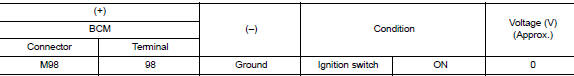
Is the inspection result normal?
YES >> GO TO 3.
NO >> Replace BCM. Refer to BCS "Removal and Installation".
3.CHECK IGNITION RELAY-1 CONTROL SIGNAL CIRCUIT (IPDM E/R)
1. Turn ignition switch OFF.
2. Disconnect BCM and IPDM E/R connectors.
3. Check continuity between BCM harness connector and IPDM E/R harness
connector.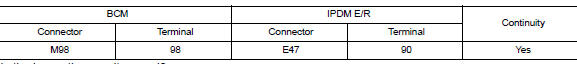
Is the inspection result normal?
YES >> Replace IPDM E/R.
NO >> Repair or replace harness.
 B261A Push-button ignition switch
Other materials:
Power steering
WARNING
If the engine is not running or is turned
off while driving, the power assist for
the steering will not work. Steering will
be harder to operate.
When the power steering warning light
illuminates with the engine running,
there will be no power assist for the
steering. You w ...
Standard maintenance
The following tables show the standard maintenance
schedule. Depending upon weather and
atmospheric conditions, varying road surfaces,
individual driving habits and vehicle usage, additional
or more frequent maintenance may be required.
After 120,000 miles
(192,000 km)/144 months, continue m ...
Categories
- Manuals Home
- Nissan Versa Owners Manual
- Nissan Versa Service Manual
- Video Guides
- Questions & Answers
- External Resources
- Latest Updates
- Most Popular
- Sitemap
- Search the site
- Privacy Policy
- Contact Us

0.006