Nissan Versa (N17): B2621 Inside antenna
DTC Logic
DTC DETECTION LOGIC 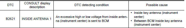
DTC CONFIRMATION PROCEDURE
1.PERFORM DTC CONFIRMATION PROCEDURE
- Select INTELLIGENT KEY of BCM using CONSULT.
- Select INSIDE ANT DIAGNOSIS in WORK SUPPORT mode.
- Perform inside key antenna (INSIDE ANT DIAGNOSIS) on WORK SUPPORT of INTELLIGENT KEY.
- Check BCM for DTC.
Is inside key antenna DTC detected?
YES >> Refer to DLK "Diagnosis Procedure".
NO >> Inside key antenna (instrument center) is OK.
Diagnosis Procedure
Regarding Wiring Diagram information, refer to DLK "INTELLIGENT KEY SYSTEM : Wiring Diagram".
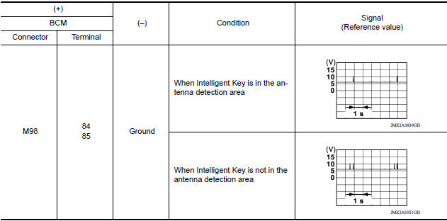
1.CHECK INSIDE KEY ANTENNA INPUT SIGNAL 1
- Turn ignition switch ON.
- Check signal between BCM harness connector and ground using
oscilloscope.
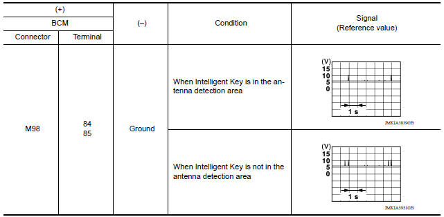
Is the inspection result normal?
YES >> Replace BCM. Refer to BCS"Removal and Installation".
NO >> GO TO 2.
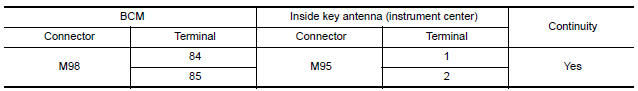
2.CHECK INSIDE KEY ANTENNA CIRCUIT
- Turn ignition switch OFF.
- Disconnect BCM connector and inside key antenna (instrument center) connector.
- Check continuity between BCM harness connector and inside key antenna
(instrument center) harness
connector.
- Check continuity between BCM harness connector and ground.
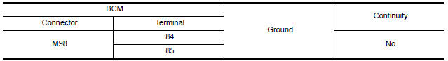
Is the inspection result normal?
YES >> GO TO 3.
NO >> Repair or replace harness.
3.CHECK INSIDE KEY ANTENNA INPUT SIGNAL 2
- Replace inside key antenna (instrument center). (New antenna or other antenna)
- Connect BCM connector and inside key antenna (instrument center) connector.
- Turn ignition switch ON.
- Check signal between BCM harness connector and ground using
oscilloscope.
Is the inspection result normal?
YES >> Replace inside key antenna (instrument center). Refer to DLK "INSTRUMENT CENTER : Removal and Installation".
NO >> Replace BCM. Refer to BCS "Removal and Installation".
 Inspection and adjustment
ADDITIONAL SERVICE WHEN REPLACING CONTROL UNIT (BCM) ...

Other materials:
Vehicle Dynamic Control (VDC) off switch
The vehicle should be driven with the VDC system
on for most driving conditions.
If the vehicle is stuck in mud or snow, the VDC
system reduces the engine output to reduce
wheel spin. The engine speed will be reduced
even if the accelerator is depressed to the floor. If
maximum engine po ...
Engine assembly
Exploded View
1. Engine mounting (RH) stay 2. Engine mount (RH) stay 3. Engine mounting
insulator (RH)
4. Rear engine mounting bracket 5. Rear torque rod 6. Engine mounting bracket
(LH)
7. Engine mounting bracket (LH) 8. Engine mounting insulator (LH) 9. Mass damper
A. Front mark B. Tra ...
Categories
- Manuals Home
- Nissan Versa Owners Manual
- Nissan Versa Service Manual
- Video Guides
- Questions & Answers
- External Resources
- Latest Updates
- Most Popular
- Sitemap
- Search the site
- Privacy Policy
- Contact Us

0.0098