Nissan Versa (N17): Bluetooth control signal circuit
Diagnosis Procedure
Regarding Wiring Diagram information, refer to AV "Wiring Diagram".
1.CHECK CONTROL SIGNAL CIRCUIT CONTINUITY
1. Turn ignition switch OFF.
2. Disconnect Bluetooth control unit connector B33.
3. Check continuity between Bluetooth control unit connector B33 and ground.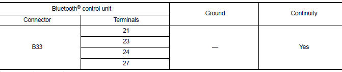
Is the inspection result normal?
YES >> Replace Bluetooth control unit. Refer to AV "Removal and Installation".
NO >> Repair or replace harness or connectors.
 Bluetooth voice signal circuit
Diagnosis Procedure Regarding Wiring Diagram information, refer to AV "Wiring Diagram". 1.CHECK BLUETOOTH VOICE SIGNAL CIRCUIT CONTINUITY 1. Turn ignition switch OFF. 2. Disconnect audio ...
Microphone signal circuit
Diagnosis Procedure Regarding Wiring Diagram information, refer to AV "Wiring Diagram". 1.CHECK HARNESS BETWEEN BLUETOOTH CONTROL UNIT AND MICROPHONE 1. Turn ignition switch OFF. 2. Di ...
Other materials:
Cleaning exterior
In order to maintain the appearance of your vehicle,
it is important to take proper care of it.
To protect the paint surfaces, please wash your
vehicle as soon as you can:
After a rainfall to prevent possible damage
from acid rain.
After driving on coastal roads.
When contaminants suc ...
Service data and specifications
(SDS)
Periodical Maintenance Specification
ENGINE OIL CAPACITY (APPROXIMATE)
...
Categories
- Manuals Home
- Nissan Versa Owners Manual
- Nissan Versa Service Manual
- Video Guides
- Questions & Answers
- External Resources
- Latest Updates
- Most Popular
- Sitemap
- Search the site
- Privacy Policy
- Contact Us

0.0047