Nissan Versa (N17): Microphone signal circuit
Diagnosis Procedure
Regarding Wiring Diagram information, refer to AV "Wiring Diagram".
1.CHECK HARNESS BETWEEN BLUETOOTH CONTROL UNIT AND MICROPHONE
1. Turn ignition switch OFF.
2. Disconnect Bluetooth control unit connector B33 and microphone connector R15.
3. Check continuity between Bluetooth control unit connector B33 and
microphone connector R15.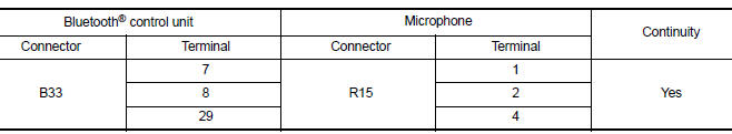
4. Check continuity between Bluetooth control unit connector B33 and ground.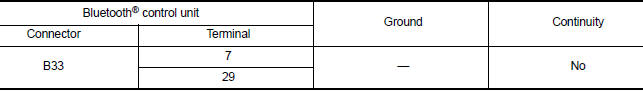
Are continuity results as specified?
YES >> GO TO 2
NO >> Repair harness or connectors.
2.CHECK MICROPHONE POWER SUPPLY
1. Connect Bluetooth control unit connector B33 and microphone connector R15.
2. Turn ignition switch ON.
3. Check voltage between microphone connector R15 and ground.
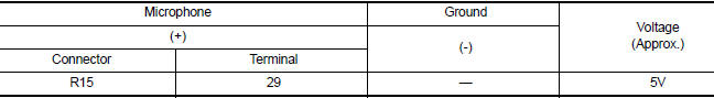
Is the voltage reading as specified?
YES >> GO TO 3
NO >> Replace Bluetooth control unit. Refer to AV"Removal and Installation".
3.CHECK MICROPHONE SIGNAL
Check signal between terminals of Bluetooth control unit connector B33.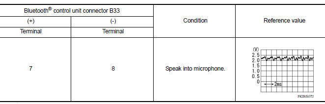
Were voltage readings as specified?
YES >> Replace Bluetooth control unit. Refer to AV "Removal and Installation".
NO >> Replace microphone. Refer to AV "Removal and Installation".
 Bluetooth control signal circuit
Diagnosis Procedure Regarding Wiring Diagram information, refer to AV "Wiring Diagram". 1.CHECK CONTROL SIGNAL CIRCUIT CONTINUITY 1. Turn ignition switch OFF. 2. Disconnect Bluetooth con ...
Steering switch
Diagnosis Procedure Regarding Wiring Diagram information, refer to AV "Wiring Diagram". 1.CHECK STEERING WHEEL AUDIO CONTROL SWITCH RESISTANCE 1. Turn ignition switch OFF. 2. Disconnect ...
Other materials:
Engine cooling system
The engine cooling system is filled at the factory
with a pre-diluted mixture of 50% Genuine
NISSAN Long Life Antifreeze/Coolant (blue) and
50% water to provide year-round antifreeze and
coolant protection. The antifreeze solution contains
rust and corrosion inhibitors. Additional engine
cooli ...
Recommended fluids/lubricants and capacities
The following are approximate capacities. The actual refill capacities may
be a little different. When refilling, follow the procedure
described in the "Do-it-yourself" section to determine the proper refill
capacity.
...
Categories
- Manuals Home
- Nissan Versa Owners Manual
- Nissan Versa Service Manual
- Video Guides
- Questions & Answers
- External Resources
- Latest Updates
- Most Popular
- Sitemap
- Search the site
- Privacy Policy
- Contact Us

0.0046