Nissan Versa (N17): Steering switch
Diagnosis Procedure
Regarding Wiring Diagram information, refer to AV "Wiring Diagram".
1.CHECK STEERING WHEEL AUDIO CONTROL SWITCH RESISTANCE
1. Turn ignition switch OFF.
2. Disconnect combination switch connector M88.
3. Check resistance between the terminals of combination switch connector
M88.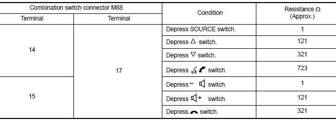
Is the inspection result normal?
YES >> GO TO 2.
NO >> Replace steering switches. Refer to AV "Removal and Installation".
2.CHECK HARNESS BETWEEN BLUETOOTH CONTROL UNIT AND COMBINATION SWITCH
1. Disconnect Bluetooth control unit connector B33 and combination switch connector M30.
2. Check continuity between Bluetooth control unit connector B33 and
combination switch connector M30.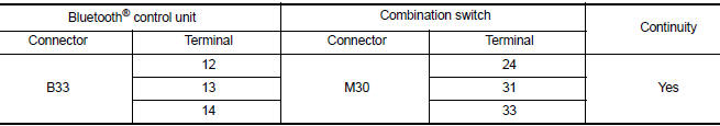
3. Check continuity between Bluetooth control unit connector B33 and ground.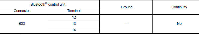
Is the inspection result normal?
YES >> GO TO 3.
NO >> Repair or replace harness or connectors.
3.CHECK COMBINATION SWITCH
Check continuity between combination switch connectors M88 and M30.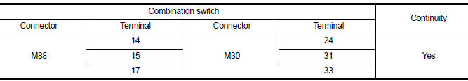
Is the inspection result normal?
YES >> GO TO 4.
NO >> Replace spiral cable. Refer to SR "Removal and Installation".
4.CHECK HARNESS BETWEEN BLUETOOTH CONTROL UNIT AND AUDIO UNIT
1. Disconnect audio unit connector M44.
2. Check continuity between Bluetooth control unit connector B33 and audio
unit connector M46.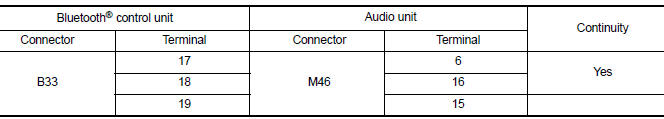
3. Check continuity between Bluetooth control unit connector B33 and ground.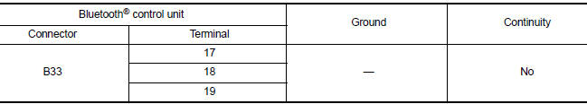
Is the inspection result normal?
YES >> Replace audio unit. Refer to AV "Removal and Installation".
NO >> Repair or replace harness or connectors.
 Microphone signal circuit
Diagnosis Procedure Regarding Wiring Diagram information, refer to AV "Wiring Diagram". 1.CHECK HARNESS BETWEEN BLUETOOTH CONTROL UNIT AND MICROPHONE 1. Turn ignition switch OFF. 2. Di ...
USB Connector
Diagnosis Procedure Regarding Wiring Diagram information, refer to AV "Wiring Diagram". 1.CHECK USB INTERFACE HARNESS CONTINUITY 1. Turn ignition switch OFF. 2. Disconnect audio unit c ...
Other materials:
Cooling fan control
Cooling fan control : system diagram
Cooling fan control : system description
INPUT/OUTPUT SIGNAL CHART
Sensor
Input signal to ECM
ECM function
Actuator
Crankshaft position sensor (POS)
Camshaft position sensor (PHASE)
Engine speed*1
Piston position
Cool ...
P0734 4GR Incorrect ratio
Description
This malfunction is detected when the A/T does not shift into 4GR position as
instructed by TCM. This is not
only caused by electrical malfunction (circuits open or shorted) but by
mechanical malfunction such as control
valve sticking, improper solenoid valve operation, etc.
DTC ...
Categories
- Manuals Home
- Nissan Versa Owners Manual
- Nissan Versa Service Manual
- Video Guides
- Questions & Answers
- External Resources
- Latest Updates
- Most Popular
- Sitemap
- Search the site
- Privacy Policy
- Contact Us

0.005