Nissan Versa (N17): USB Connector
Diagnosis Procedure
Regarding Wiring Diagram information, refer to AV "Wiring Diagram".
1.CHECK USB INTERFACE HARNESS CONTINUITY
1. Turn ignition switch OFF.
2. Disconnect audio unit connector M48 and USB interface connector M72.
3. Check continuity between audio unit connector M48 and USB interface
connector M72.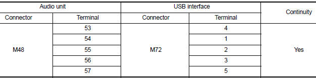
4. Check continuity between audio unit connector M48 and ground.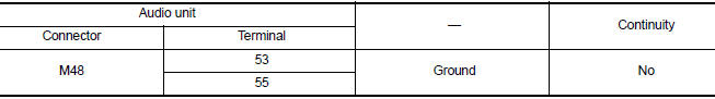
Is the inspection result normal?
YES >> Replace the USB interface. Refer to AV "Removal and Installation".
NO >> Repair or replace harness or connectors.
SYMPTOM DIAGNOSIS
 Steering switch
Diagnosis Procedure Regarding Wiring Diagram information, refer to AV "Wiring Diagram". 1.CHECK STEERING WHEEL AUDIO CONTROL SWITCH RESISTANCE 1. Turn ignition switch OFF. 2. Disconnect ...
Audio system
Symptom Table RELATED TO AUDIO RELATED TO HANDS-FREE PHONE Before performing diagnosis, confirm that the cellular phone being used by the customer is compatible with the vehicle. It i ...
Other materials:
Interior lights
The interior light has a three-position switch and
operates regardless of ignition switch position.
When the switch is in the ON position 1 , the
interior lights illuminate, regardless of door position.
The lights will go off after a period of time
unless the ignition switch is placed i ...
Intake manifold
Exploded View
1. EVAP canister purge volume control
solenoid valve
2. Hose clamp 3. Vacuum hose
4. PCV hose 5. Hose clamp 6. Intake manifold support
7. Gasket 8. Intake manifold 9. Electric throttle control actuator
10. Gasket 11. EVAP service port
A. To air duct B. To centralized underf ...
Categories
- Manuals Home
- Nissan Versa Owners Manual
- Nissan Versa Service Manual
- Video Guides
- Questions & Answers
- External Resources
- Latest Updates
- Most Popular
- Sitemap
- Search the site
- Privacy Policy
- Contact Us

0.006