Nissan Versa (N17): Body alignment
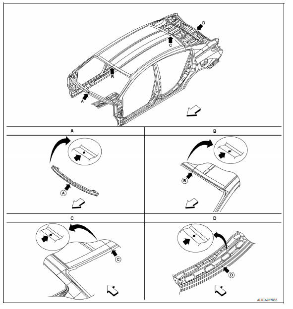
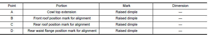
Body Center Marks
A mark has been placed on each part of the body to indicate the vehicle center. When repairing parts damaged by an accident which might affect the vehicle frame (members, pillars, etc.), more accurate and effective repair will be possible by using these marks together with body alignment specifications.
 Front
Front
Description
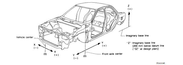
- All dimensions indicated as shown are actual.
- When using a tracking gauge, adjust both pointers to equal length. Then check the pointers and gauge itself to make sure there is no free play.
- When a measuring tape is used, check to be sure there is no elongation, twisting or bending.
- Measurements should be taken at the center of the mounting holes.
- An asterisk (*) following the value at the measuring point indicates that the measuring point on the other side is symmetrically the same value.
- The coordinates of the measurement points are the distances measured from the standard line of ″X″, ″Y″ and ″Z″.
Engine Compartment
Measurement
* Figures marked with an * indicate symmetrically identical dimensions on both RH and LH sides of the vehicle.
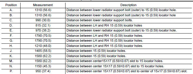
Underbody
Measurement
 Front
Front
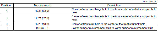
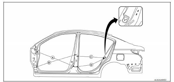
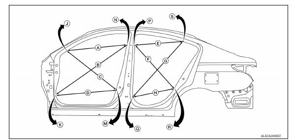
Passenger Compartment
Measurement
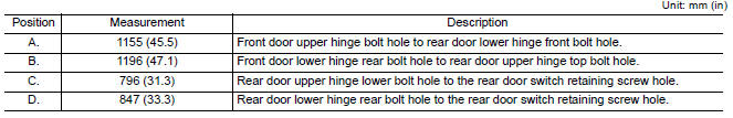
* The vehicle is symmetrically identical dimensions on both RH and LH sides of the vehicle.
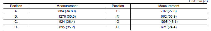
* The vehicle is symmetrically identical dimensions on both RH and LH sides of the vehicle.
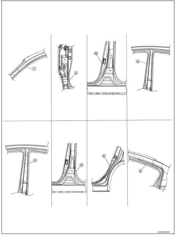
Measurement Points
Rear End Panel
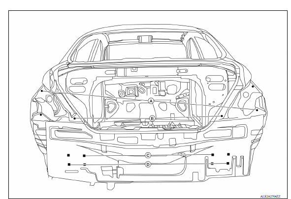
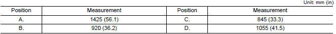
* The vehicle is symmetrically identical dimensions on both RH and LH sides of the vehicle.
 Replacement operations
Description This section is prepared for technicians who have attained a high level of skill and experience in repairing collision- damaged vehicles and also use modern service tools and equipme ...

Other materials:
Instrument panel
1. Headlight/turn signal switch/fog light
switch (if so equipped)
2. Driver's supplemental air bag (P. 1-39)
Horn
3. Meters and gauges. Warning and indicator lights
4. Wiper and washer switch
5. Vents
6. Rear window defroster switch
7. Front passenger air bag status light
8. Hazard warn ...
Oil pump
Exploded View
1. Rear oil seal 2. Oring 3. Oil pan (upper)
4. Oil pump chain tensioner (for oil
pump drive chain)
5. Oil pump drive chain 6. Crankshaft key
7. Crankshaft sprocket 8. Oil pump sprocket 9. Oil pump
10. Oring 11. Oring 12. Oil pan drain plug
13. Drain plug washer 14. Oil pan ( ...
Categories
- Manuals Home
- Nissan Versa Owners Manual
- Nissan Versa Service Manual
- Video Guides
- Questions & Answers
- External Resources
- Latest Updates
- Most Popular
- Sitemap
- Search the site
- Privacy Policy
- Contact Us

0.0056