Nissan Versa (N17): Combination meter
Removal and Installation
REMOVAL
1. Disconnect the negative battery terminal. Refer to PG "Removal and Installation".
2. Remove cluster lid A. Refer to IP "Removal and Installation".
3. Remove the combination meter screws.
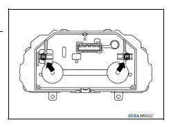
4. Pull the combination meter straight out to disengage resin clips.
NOTE: The illustration shows the clip positions on the back of the combination meter.
5. Disconnect the harness connector from the combination meter and remove.
INSTALLATION
Installation is in the reverse order of removal.
UNIT DISASSEMBLY AND ASSEMBLY
 The low washer fluid warning continues
displaying, or does not display
The low washer fluid warning continues
displaying, or does not display
Description The warning is still displayed even after washer fluid is added. The warning is not displayed even though the washer tank is empty. Diagnosis Procedure 1.CHECK WASHER FLUID LEV ...
Combination meter
Exploded View 1. Unified meter control unit 2. Front cover 3. Finisher Disassembly and Assembly DISASSEMBLY 1. Disengage the pawls of the finisher using a suitable tool and remove the fini ...
Other materials:
Vehicle Dynamic Control (VDC) off switch
The vehicle should be driven with the VDC system
on for most driving conditions.
If the vehicle is stuck in mud or snow, the VDC
system reduces the engine output to reduce
wheel spin. The engine speed will be reduced
even if the accelerator is depressed to the floor. If
maximum engine po ...
Engine cooling system
The engine cooling system is filled at the factory
with a pre-diluted mixture of 50% Genuine
NISSAN Long Life Antifreeze/Coolant (blue) and
50% water to provide year-round antifreeze and
coolant protection. The antifreeze solution contains
rust and corrosion inhibitors. Additional engine
cooli ...
Categories
- Manuals Home
- Nissan Versa Owners Manual
- Nissan Versa Service Manual
- Video Guides
- Questions & Answers
- External Resources
- Latest Updates
- Most Popular
- Sitemap
- Search the site
- Privacy Policy
- Contact Us

0.0051