Nissan Versa (N17): Power supply and ground circuit
Combination meter (type A)
COMBINATION METER (TYPE A) : Diagnosis Procedure
Regarding Wiring Diagram information, refer to MWI"Wiring Diagram".
1.CHECK FUSE
Check for blown combination meter fuses.

Is the inspection result normal?
YES >> GO TO 2.
NO >> Replace the fuse after repairing the affected circuit.
2.CHECK POWER SUPPLY CIRCUIT
Check voltage between combination meter harness connector and ground.
1. Turn ignition switch to OFF.
2. Disconnect combination meter connector.
3. Check voltage between combination meter harness connector M24 terminals 1,
3 and ground. 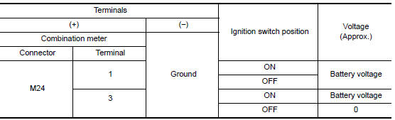
Is the inspection result normal?
YES >> GO TO 3.
NO >> Check harness between combination meter and fuse.
3.CHECK GROUND CIRCUIT
1. Turn ignition switch OFF.
2. Check continuity between combination meter harness connector M24 terminals
21, 22, 23 and ground.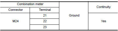
Is the inspection result normal?
YES >> INSPECTION END
NO >> Repair harness or connector.
Combination meter (type B)
COMBINATION METER (TYPE B) : Diagnosis Procedure
Regarding Wiring Diagram information, refer to MWI "Wiring Diagram".
1.CHECK FUSE
Check for blown combination meter fuses.

Is the inspection result normal?
YES >> GO TO 2.
NO >> Replace the fuse after repairing the affected circuit.
2.POWER SUPPLY CIRCUIT CHECK
1. Disconnect combination meter connector.
2. Check voltage between combination meter harness connector M82, terminals
27, 28, 15 and ground.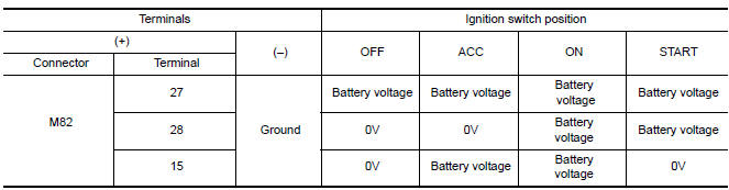
Is the inspection result normal?
YES >> GO TO 3.
NO >> Check harness for open between combination meter and fuse.
3.GROUND CIRCUIT CHECK
1. Turn ignition switch OFF.
2. Disconnect combination meter connector.
3. Check continuity between combination meter harness connector M82,
terminals 21, 22, 23 and ground.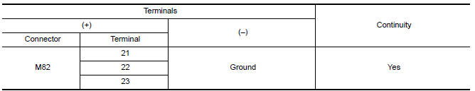
Is the inspection result normal?
YES >> Inspection End.
NO >> Check ground harness.
BCM (Body control system) (with intelligent key system)
BCM (BODY CONTROL SYSTEM) (WITH INTELLIGENT KEY SYSTEM) : Diagnosis Procedure
Regarding Wiring Diagram information, refer to BCS "Wiring Diagram".
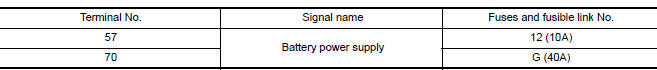
1.CHECK FUSES AND FUSIBLE LINK
Check that the following fuses and fusible link are not blown.
Is the fuse blown?
YES >> Replace the blown fuse or fusible link after repairing the affected circuit.
NO >> GO TO 2.
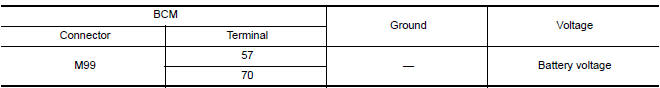
2.CHECK POWER SUPPLY CIRCUIT
1. Disconnect BCM connector M99.
2. Check voltage between BCM connector M99 and ground.
Is the inspection result normal?
YES >> GO TO 3.
NO >> Repair harness or connector.
3.CHECK GROUND CIRCUIT
Check continuity between BCM connector M99 and ground.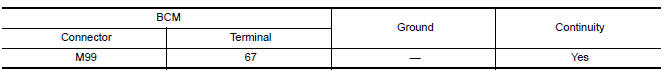
Is the inspection result normal?
YES >> Inspection End.
NO >> Repair harness or connector.
BCM (Body control system) (without intelligent key system)
BCM (BODY CONTROL SYSTEM) (WITHOUT INTELLIGENT KEY SYSTEM) : Diagnosis Procedure
Regarding Wiring Diagram information, refer to BCS "Wiring Diagram".
1.CHECK FUSES AND FUSIBLE LINK
Check that the following fuses and fusible link are not blown.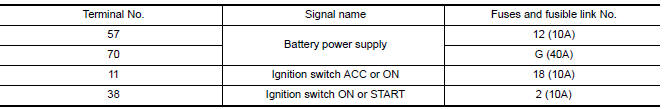
Is the fuse blown?
YES >> Replace the blown fuse or fusible link after repairing the affected circuit.
NO >> GO TO 2.
2.CHECK POWER SUPPLY CIRCUIT
1. Turn ignition switch OFF.
2. Disconnect BCM connectors.
3. Check voltage between BCM connector and ground.
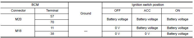
Is the inspection result normal?
YES >> GO TO 3.
NO >> Repair harness or connector.
3.CHECK GROUND CIRCUIT
Check continuity between BCM connector and ground.
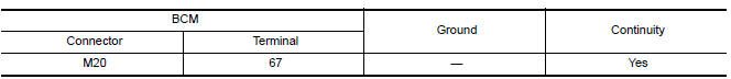
Is the inspection result normal?
YES >> Inspection End.
NO >> Repair harness or connector.
 Diagnosis and repair workflow
Work Flow OVERALL SEQUENCE DETAILED FLOW 1.OBTAIN INFORMATION ABOUT SYMPTOM Interview the customer to obtain as much information as possible about the conditions and environment under whic ...

Other materials:
EVAP canister vent control valve
Exploded View
1. EVAP canister 2. O-ring 3. EVAP canister vent control valve
4. EVAP canister vent control valve hose
Removal and Installation
NOTE:
The EVAP canister vent control valve can be removed without removing the EVAP
canister.
REMOVAL
Remove the EVAP canister protector cov ...
Headlining
Exploded View
1. Headlining assembly 2. Sun visor assembly (RH) 3. Sun visor assembly (RH)
4. Map lamp (if equipped) 5. Sun visor holder (LH) 6. Sun visor assembly (LH)
7. Microphone finisher (if equipped) 8. Room lamp 9. Front assist grip (RH) (if
equipped)
10. Rear assist grip (RH) (if ...
Categories
- Manuals Home
- Nissan Versa Owners Manual
- Nissan Versa Service Manual
- Video Guides
- Questions & Answers
- External Resources
- Latest Updates
- Most Popular
- Sitemap
- Search the site
- Privacy Policy
- Contact Us

0.0079