Nissan Versa (N17): Fuel level sensor signal circuit
Description
The fuel level sensor unit and fuel pump detects the approximate fuel level in the fuel tank and transmits the fuel level signal to the combination meter.
Component Function Check
1.COMBINATION METER INPUT SIGNAL
1. Select METER/M&A on CONSULT.
2. Using FUEL METER of DATA MONITOR, compare the DATA MONITOR value with the
fuel gauge position.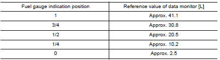
Does monitor value match fuel gauge reading?
YES >> Inspection End.
NO >> Replace combination meter. Refer to MWI "Removal and Installation".
Diagnosis Procedure
Regarding Wiring Diagram information, refer to MWI "Wiring Diagram".
1.CHECK HARNESS CONNECTOR
1. Turn ignition switch OFF.
2. Check combination meter and fuel level sensor unit terminals (meter-side and harness-side) for poor connection.
Is the inspection result normal?
YES >> GO TO 2
NO >> Repair or replace terminals or connectors.
2.CHECK FUEL LEVEL SENSOR UNIT CIRCUIT
1. Disconnect combination meter harness connector M24 and fuel level sensor unit and fuel pump harness connector B44.
2. Check continuity between combination meter harness connector M24 terminal
4 and fuel level sensor unit
and fuel pump harness connector B44 terminal 2. 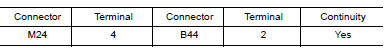
3. Check continuity between fuel level sensor unit and fuel pump harness
connector B44 terminal 2 and
ground. 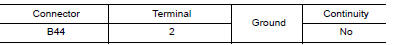
Is the inspection result normal?
YES >> GO TO 3
NO >> Repair harness or connector.
3.CHECK FUEL LEVEL SENSOR GROUND CIRCUIT
1. Check continuity between combination meter harness connector M24 terminal
26 and fuel level sensor
unit and fuel pump harness connector B44 terminal 5. 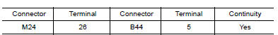
2. Check continuity between fuel level sensor unit and fuel pump harness
connector B44 terminal 5 and
ground. 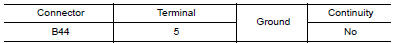
Is the inspection result normal?
YES >> GO TO 4
NO >> Repair harness or connector.
4.CHECK INSTALLATION CONDITION
Check fuel level sensor unit installation, and verify the float arm does not interfere or bind with the internal components in the fuel tank.
Is the inspection result normal?
YES >> Inspection End.
NO >> Install the fuel level sensor unit properly.
Component Inspection
1.REMOVE FUEL LEVEL SENSOR UNIT
Remove the fuel level sensor unit. Refer to FL"Removal and Installation".
>> GO TO 2.
2.CHECK FUEL LEVEL SENSOR UNIT
Check the resistance between fuel level sensor unit and fuel pump. 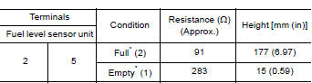
*: When float rod is in contact with stopper.
Is inspection result OK?
YES >> Inspection End.
NO >> Replace fuel level sensor unit and fuel pump. Refer to
FL "Removal and Installation".
 Power supply and ground circuit
Washer fluid level switch circuit
Description Transmits the washer fluid level switch signal to the combination meter. ...
Other materials:
Maintenance under severe operating conditions
The maintenance intervals shown on the preceding pages are for normal
operating conditions. If the vehicle is mainly operated under severe driving
conditions as shown below, more frequent maintenance must be performed on the
following items as shown in the table.
Severe driving conditions
...
Clutch master cylinder
Exploded View
1. Reservoir hose 2. Master cylinder
Removal and Installation
CAUTION:
Do not spill clutch fluid onto painted surfaces. If fluid spills,
wipe up immediately and wash the
affected area with water.
Do not disassemble clutch master cylinder.
NOTE:
When removing compo ...
Categories
- Manuals Home
- Nissan Versa Owners Manual
- Nissan Versa Service Manual
- Video Guides
- Questions & Answers
- External Resources
- Latest Updates
- Most Popular
- Sitemap
- Search the site
- Privacy Policy
- Contact Us

0.0095