Nissan Versa (N17): B2556 Push-button ignition switch
DTC Logic
DTC DETECTION LOGIC 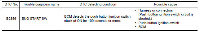
DTC CONFIRMATION PROCEDURE
1.PERFORM DTC CONFIRMATION PROCEDURE
1. Press push-button ignition switch under the following condition.
- Brake pedal: Not depressed
2. Release push-button ignition switch and wait 100 seconds or more.
3. Check DTC in Self Diagnostic Result mode of BCM using CONSULT.
Is DTC detected?
YES >> Go to SEC "Diagnosis Procedure".
NO >> Inspection End.
Diagnosis Procedure
Regarding Wiring Diagram information, refer to SEC "Wiring Diagram".
1.CHECK PUSH-BUTTON IGNITION SWITCH INPUT SIGNAL
1. Turn ignition switch OFF.
2. Disconnect push-button ignition switch connector.
3. Check voltage between push-button ignition switch harness connector and
ground. 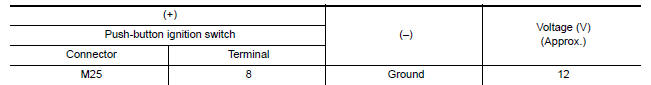
Is the inspection result normal?
YES >> GO TO 4.
NO >> GO TO 2.
2.CHECK PUSH-BUTTON IGNITION SWITCH CIRCUIT
1. Disconnect BCM connector and IPDM E/R connector.
2. Check continuity between push-button ignition switch harness connector and
BCM harness connector.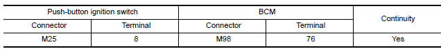
3. Check continuity between push-button ignition switch harness connector and
ground.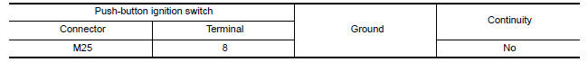
Is the inspection result normal?
YES >> GO TO 3.
NO >> Repair or replace harness.
3.REPLACE BCM
1. Replace BCM. Refer to BCS "Removal and Installation".
2. Perform initialization of BCM and registration of all Intelligent Keys using CONSULT.
>> Inspection End.
4.CHECK PUSH-BUTTON IGNITION SWITCH GROUND CIRCUIT
Check continuity between push-button ignition switch harness connector and
ground. 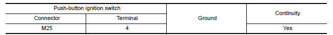
Is the inspection result normal?
YES >> GO TO 5.
NO >> Repair or replace harness.
5.CHECK PUSH-BUTTON IGNITION SWITCH
Refer to SEC "Component Inspection".
Is the inspection result normal?
YES >> GO TO 6.
NO >> Replace push-button ignition switch. Refer to SEC "Removal and Installation".
6.CHECK INTERMITTENT INCIDENT
Refer to GI "Intermittent Incident".
>> Inspection End.
Component Inspection
1.CHECK PUSH-BUTTON IGNITION SWITCH
1. Turn ignition switch OFF.
2. Disconnect push-button ignition switch connector.
3. Check continuity between push-button ignition switch terminals. 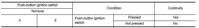
Is the inspection reult normal?
YES >> Inspection End.
NO >> Replace push-button ignition switch. Refer to SEC "Removal and Installation".
 B2555 Stop lamp
Other materials:
Specifications
Engine
This spark ignition system complies with the Canadian standard ICES-002.
Wheels and tires
Dimensions and weights
...
P074A Unable to engage 2GR
Description
This malfunction is detected when the A/T does not shift into 2GR position as
instructed by TCM. This is not
only caused by electrical malfunction (circuits open or shorted) but by
mechanical malfunction such as control
valve sticking, improper solenoid valve operation, etc.
DTC ...
Categories
- Manuals Home
- Nissan Versa Owners Manual
- Nissan Versa Service Manual
- Video Guides
- Questions & Answers
- External Resources
- Latest Updates
- Most Popular
- Sitemap
- Search the site
- Privacy Policy
- Contact Us

0.0053