Nissan Versa (N17): Fuel level sensor signal circuit
Description
The fuel level sensor unit and fuel pump detects the approximate fuel level in the fuel tank and transmits the fuel level signal to the combination meter.
Component Function Check
1.COMBINATION METER INPUT SIGNAL
1. Select METER/M&A on CONSULT.
2. Using FUEL METER of DATA MONITOR, compare the DATA MONITOR value with the
fuel gauge position.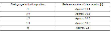
Does monitor value match fuel gauge reading?
YES >> Inspection End.
NO >> Replace combination meter. Refer to MWI "Removal and Installation".
Diagnosis Procedure
Regarding Wiring Diagram information, refer to MWI "Wiring Diagram".
1.CHECK HARNESS CONNECTOR
1. Turn ignition switch OFF.
2. Check combination meter and fuel level sensor unit terminals (meter-side and harness-side) for poor connection.
Is the inspection result normal?
YES >> GO TO 2
NO >> Repair or replace terminals or connectors.
2.CHECK FUEL LEVEL SENSOR UNIT CIRCUIT
1. Disconnect combination meter harness connector M82 and fuel level sensor unit and fuel pump harness connector B44.
2. Check continuity between combination meter harness connector M82 terminal
6 and fuel level sensor unit
and fuel pump harness connector B44 terminal 2. 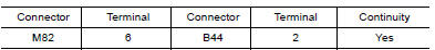
3. Check continuity between fuel level sensor unit and fuel pump harness
connector B44 terminal 2 and
ground. 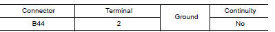
Is the inspection result normal?
YES >> GO TO 3
NO >> Repair harness or connector.
3.CHECK FUEL LEVEL SENSOR GROUND CIRCUIT
1. Check continuity between combination meter harness connector M82 terminal
24 and fuel level sensor
unit and fuel pump harness connector B44 terminal 5. 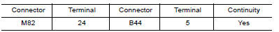
2. Check continuity between fuel level sensor unit and fuel pump harness
connector B44 terminal 5 and
ground. 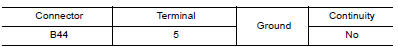
Is the inspection result normal?
YES >> GO TO 4
NO >> Repair harness or connector.
4.CHECK INSTALLATION CONDITION
Check fuel level sensor unit installation, and verify the float arm does not interfere or bind with the internal components in the fuel tank.
Is the inspection result normal?
YES >> Inspection End.
NO >> Install the fuel level sensor unit properly.
Component Inspection
1.REMOVE FUEL LEVEL SENSOR UNIT
Remove the fuel level sensor unit. Refer to FL "Removal and Installation".
>> GO TO 2.
2.CHECK FUEL LEVEL SENSOR UNIT
Check the resistance between fuel level sensor unit and fuel pump. 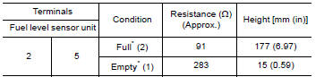
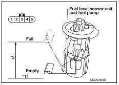
*: When float rod is in contact with stopper.
Is inspection result OK?
YES >> Inspection End.
NO >> Replace fuel level sensor unit and fuel pump. Refer to
FL "Removal and Installation".
 Power supply and ground circuit
Washer fluid level switch circuit
Description Transmits the washer fluid level switch signal to the combination meter. Diagnosis Procedure Regarding Wiring Diagram information, refer to MWI "Wiring Diagram". 1.CHECK WA ...
Other materials:
Rear window defroster switch
To defrost the rear window glass, start the engine
and push the rear window defroster switch on.
The rear window defroster indicator light on the
switch comes on. Push the switch again to turn
the defroster off.
The rear window defroster automatically turns off
after approximately 15 m ...
RearView Monitor (if so equipped)
1. CAMERA button (models with navigation)
WARNING
Failure to follow the warnings and instructions
for proper use of the Rear-
View Monitor system could result in serious
injury or death.
RearView Monitor is a convenience feature
and is not a substitute for proper
backing. Always ...
Categories
- Manuals Home
- Nissan Versa Owners Manual
- Nissan Versa Service Manual
- Video Guides
- Questions & Answers
- External Resources
- Latest Updates
- Most Popular
- Sitemap
- Search the site
- Privacy Policy
- Contact Us

0.0084