Nissan Versa (N17): Washer fluid level switch circuit
Description
Transmits the washer fluid level switch signal to the combination meter.
Diagnosis Procedure
Regarding Wiring Diagram information, refer to MWI "Wiring Diagram".
1.CHECK WASHER FLUID LEVEL SWITCH SIGNAL CIRCUIT
1. Turn ignition switch OFF.
2. Disconnect combination meter connector M82 and washer fluid level switch connector E50.
3. Check continuity between combination meter harness connector M82 terminal
17 and washer fluid level
switch harness connector E50 terminal 1. 
4. Check continuity between combination meter harness connector M82 terminal
17 and ground.
Is the inspection result normal?
YES >> GO TO 2.
NO >> Repair or replace harness or connector.
2.CHECK WASHER FLUID LEVEL SWITCH GROUND CIRCUIT
Check continuity between washer fluid level switch harness connector E50
terminal 2 and ground.
Is the inspection result normal?
YES >> Inspection End.
NO >> Repair or replace harness or connector.
Component Inspection
1.CHECK WASHER FLUID LEVEL SWITCH
Check continuity between washer fluid level switch terminals 1 and 2. 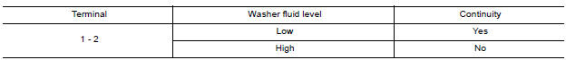
Is the inspection result normal?
YES >> Inspection End.
NO >> Replace washer fluid level switch.Refer to WW "Exploded View".
SYMPTOM DIAGNOSIS
 Fuel level sensor signal circuit
Description The fuel level sensor unit and fuel pump detects the approximate fuel level in the fuel tank and transmits the fuel level signal to the combination meter. Component Function Check 1. ...
The fuel gauge indicator does not
operate
Description Fuel gauge will not indicate from a certain position. Diagnosis Procedure 1.CHECK COMBINATION METER INPUT SIGNAL 1. Select METER/M&A on CONSULT. 2. Using "DATA MONITOR, compar ...
Other materials:
Clutch pedal
Inspection and Adjustment
1. Check to see if the master cylinder rod end moves freely.
It
should not be bound by the clutch pedal.
a. If the rod end does not move freely, remove the rod end and
check for deformation or damage on the rod end. Leave the rod
end removed ...
P0979 Shift solenoid C
DTC Logic
DTC DETECTION LOGIC
DTC
Trouble diagnosis name
DTC detection condition
Possible causes
P0979
Shift Solenoid C Control Circuit
Low
The following diagnosis conditions
are met, and the current
monitor reading of the TCM 2-4
brake solenoid valve is ...
Categories
- Manuals Home
- Nissan Versa Owners Manual
- Nissan Versa Service Manual
- Video Guides
- Questions & Answers
- External Resources
- Latest Updates
- Most Popular
- Sitemap
- Search the site
- Privacy Policy
- Contact Us

0.0056