Nissan Versa (N17): Diagnosis and repair workflow
Work Flow
OVERALL SEQUENCE
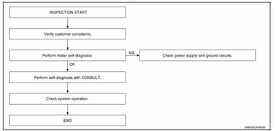
DETAILED FLOW
1.CONFIRM SYMPTOM
Confirm symptom or customer complaint.
>> GO TO 2
2.SELF-DIAGNOSIS OF COMBINATION METER
Perform self-diagnosis of combination meter. Refer to MWI "Diagnosis Description".
Is the inspection result normal?
YES >> GO TO 3
NO >> If self-diagnosis will not start, check power supply and ground circuit of combination meter. Refer to MWI "COMBINATION METER : Diagnosis Procedure". If power supply and ground circuits are OK, replace combination meter. Refer to MWI "Removal and Installation".
3.CHECK COMBINATION METER WITH CONSULT
Select "METER/M&A" on CONSULT and perform self-diagnosis of combination meter. Refer to MWI "CONSULT Function".
Is the inspection result normal?
YES >> Check symptom. GO TO 4.
NO >> Refer to MWI"DTC Index".
4.CHECK SYSTEM OPERATION
Check the combination meter to verify that the repair has been completed successfully.
Is the inspection result normal?
YES >> Inspection End.
NO >> GO TO 1
DTC/CIRCUIT DIAGNOSIS
 Diagnosis system (combination
meter)
Diagnosis system (combination
meter)U1000 CAN Comm circuit
DTC Logic DTC DETECTION LOGIC Diagnosis Procedure 1.CHECK DTC DETECTION With CONSULT. 1. Turn ignition switch OFF to ON. 2. Perform self diagnostic result. Is DTC U1000 det ...
Other materials:
Doors
When the doors are locked using one of the
following methods, the doors cannot be opened
using the inside or outside door handles. The
doors must be unlocked to open the doors.
WARNING
Before opening any door, always look
for and avoid oncoming traffic.
To help avoid risk of injury or de ...
When traveling or registering in another country
When planning to drive your NISSAN vehicle
in another country, you should first find
out if the fuel available is suitable for your vehicle's
engine.
Using fuel with an octane rating that is too low
may cause engine damage. All gasoline vehicles
must be operated with unleaded gasoline. There ...
Categories
- Manuals Home
- Nissan Versa Owners Manual
- Nissan Versa Service Manual
- Video Guides
- Questions & Answers
- External Resources
- Latest Updates
- Most Popular
- Sitemap
- Search the site
- Privacy Policy
- Contact Us

0.0065