Nissan Versa (N17): Diagnosis and repair workflow
Work Flow
OVERALL SEQUENCE
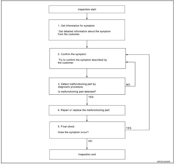
DETAILED FLOW
1.GET INFORMATION FOR SYMPTOM
Get detailed information from the customer about the symptom (the condition and the environment when the incident/malfunction occurred).
>> GO TO 2.
2.CONFIRM THE SYMPTOM
Try to confirm the symptom described by the customer. Verify relation between the symptom and the condition when the symptom is detected. Refer to AV "Symptom Table".
>> GO TO 3.
3.DETECT MALFUNCTIONING PART BY DIAGNOSTIC PROCEDURE
Inspect according to Diagnostic Procedure of the system
Is malfunctioning part detected?
YES >> GO TO 4.
NO >> GO TO 2.
4.REPAIR OR REPLACE THE MALFUNCTIONING PART
1. Repair or replace the malfunctioning part.
2. Reconnect parts or connectors disconnected during Diagnostic Procedure.
>> GO TO 5.
5.FINAL CHECK
Refer to confirmed symptom in step 2, and make sure that the symptom is not detected.
Has the symptom been repaired?
YES >> Inspection End.
NO >> GO TO 2.
DTC/CIRCUIT DIAGNOSIS
 Audio system
AUDIO SYSTEM : System Diagram AUDIO SYSTEM : System Description AUDIO SYSTEM The audio system consists of the following components Audio unit Front door speakers Rear door speakers ...
Power supply and ground circuit
AUDIO UNIT AUDIO UNIT : Diagnosis Procedure Regarding Wiring Diagram information, refer to AV "Wiring Diagram". 1.CHECK FUSES Check that the following fuses are not blown. & ...
Other materials:
Parking/parking on hills
WARNING
Do not stop or park the vehicle over
flammable materials such as dry grass,
waste paper or rags. They may ignite
and cause a fire.
Safe parking procedures require that
both the parking brake be set and the
transmission placed into P (Park) or in
an appropriate gear for ...
Vehicle identification
Vehicle identification number (VIN) plate
The vehicle identification number (VIN) plate is
attached as shown. This number is the identification
for your vehicle and is used in the vehicle
registration.
Vehicle identification number (chassis number)
The vehicle identification number i ...
Categories
- Manuals Home
- Nissan Versa Owners Manual
- Nissan Versa Service Manual
- Video Guides
- Questions & Answers
- External Resources
- Latest Updates
- Most Popular
- Sitemap
- Search the site
- Privacy Policy
- Contact Us

0.0048