Nissan Versa (N17): P0847 Transmission fluid pressure SEN/SW B
DTC Logic
DTC DETECTION LOGIC
| DTC | Trouble diagnosis name | DTC detection condition | Possible causes |
| P0847 | Transmission Fluid Pressure Sensor/Switch B Circuit Low | The secondary pressure sensor voltage is
0.09 V or less continuously for 5 seconds or
more under the following diagnosis conditions: - Diagnosis conditions - CVT fluid temperature: −20C (−4F) or more - TCM power supply voltage: More than 11 V |
- Harness or connector
(Secondary pressure sensor circuit is
open or shorted to ground) - Secondary pressure sensor - Control valve assembly |
DTC CONFIRMATION PROCEDURE
1.PREPARATION BEFORE WORK
If another "DTC CONFIRMATION PROCEDURE" occurs just before, turn ignition switch OFF and wait for at least 10 seconds, then perform the next test.
>> GO TO 2.
2.CHECK DTC DETECTION
With CONSULT
- Start the engine.
- Select "Data Monitor" in "TRANSMISSION".
- Select "FLUID TEMP".
- Maintain the following conditions for 10 seconds or more.
- Check the first trip DTC.
FLUID TEMP : −19C (−2.2F) or more
With GST
- Start the engine and wait for at least 10 seconds.
CAUTION: When the ambient temperature is −20C (−4F) or less and the engine is cold, warm up the engine for approximately 5 minutes.
- Check the first trip DTC.
Is "P0847"detected?
YES >> Go to TM "Diagnosis Procedure".
NO >> INSPECTION END
Diagnosis Procedure
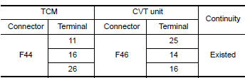
1.CHECK CIRCUIT BETWEEN TCM AND CVT UNIT (PART 1)
- Turn ignition switch OFF.
- Disconnect TCM connector and CVT unit connector.
- Check continuity between TCM harness connector terminals and CVT unit
harness connector terminals.
Is the inspection result normal?
YES >> GO TO 2.
NO >> Repair or replace malfunctioning parts.
2.CHECK CIRCUIT BETWEEN TCM AND CVT UNIT (PART 2)
Check continuity between TCM harness connector terminals and ground. 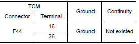
Is the inspection result normal?
YES >> GO TO 3.
NO >> Repair or replace malfunctioning parts.
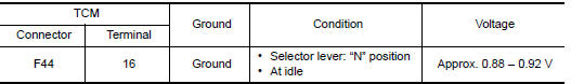
3.CHECK TCM INPUT SIGNALS
- Connect all connectors removed.
- Start the engine.
- Check voltage between TCM harness connector terminal and ground.
Is the inspection result normal?
YES >> Check intermittent incident. Refer to GI "Intermittent Incident".
NO >> There is malfunction of secondary pressure sensor. Replace transaxle assembly. Refer to TM "Removal and Installation".
 P0846 Transmission fluid pressure
SEN/SW B
P0846 Transmission fluid pressure
SEN/SW B
DTC Logic DTC DETECTION LOGIC DTC Trouble diagnosis name DTC detection condition Possible causes P0846 Transmission Fluid Pressure Sensor/Switch B Circuit Range/Per ...

Other materials:
Event Data Recorders (EDR)
This vehicle is equipped with an Event Data Recorder
(EDR). The main purpose of an EDR is to
record, in certain crash or near crash-like situations,
such as an air bag deployment or hitting a
road obstacle, data that will assist in understanding
how a vehicle's systems performed. The EDR
is de ...
Excessive ABS Function operation
frequency
Diagnosis Procedure
1.CHECK START
Check front and rear brake force distribution using a brake tester.
Is the inspection result normal?
YES >> GO TO 2
NO >> Check brake system.
2.CHECK FRONT AND REAR AXLE
Make sure that there is no excessive play in the front and rear axles. Refer ...
Categories
- Manuals Home
- Nissan Versa Owners Manual
- Nissan Versa Service Manual
- Video Guides
- Questions & Answers
- External Resources
- Latest Updates
- Most Popular
- Sitemap
- Search the site
- Privacy Policy
- Contact Us

0.0051