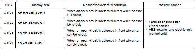
Nissan Versa (N17): C1101, C1102, C1103, C1104 Wheel sensor
DTC Logic
DTC DETECTION LOGIC
DTC CONFIRMATION PROCEDURE
1.CHECK SELF DIAGNOSTIC RESULT
With CONSULT.
- Start engine and drive vehicle at approximately 30 km/h (19 MPH) or more for approximately 1 minute.
- Perform self diagnostic result.
Is DTC C1101, C1102, C1103 or C1104 detected?
YES >> Proceed to diagnosis procedure. Refer to BRC "Diagnosis Procedure".
NO >> Inspection End.
Diagnosis Procedure
Regarding Wiring Diagram information, refer to BRC "Wiring Diagram".
CAUTION: Do not check between wheel sensor terminals.
1.CONNECTOR INSPECTION
- Disconnect ABS actuator and electric unit (control unit) connector E33 and wheel sensor connector of wheel with DTC.
- Check connectors and terminals for deformation, disconnection, looseness or damage.
Is the inspection result normal?
YES >> GO TO 2
NO >> Repair or replace as necessary.
2.CHECK WHEEL SENSOR OUTPUT SIGNAL
- Connect ABS active wheel sensor tester (J-45741) to wheel sensor using appropriate adapter.
- Turn on the ABS active wheel sensor tester power switch.
NOTE: The green POWER indicator should illuminate. If the POWER indicator does not illuminate, replace the battery in the ABS active wheel sensor tester before proceeding.
- Spin the wheel of the vehicle by hand and observe the red SENSOR
indicator on the ABS active wheel
sensor tester. The red SENSOR indicator should flash on and off to indicate
an output signal.
NOTE: If the red SENSOR indicator illuminates but does not flash, reverse the polarity of the tester leads and retest.
Does the ABS active wheel sensor tester detect a signal?
YES >> GO TO 3
NO >> Replace the wheel sensor. Refer to BRC "FRONT WHEEL SENSOR : Removal and Installation" (front) or BRC "REAR WHEEL SENSOR : Removal and Installation" (rear).
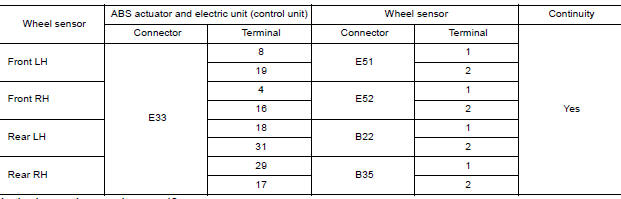
3.CHECK WIRING HARNESS FOR OPEN CIRCUIT
Check continuity between ABS actuator and electric unit (control unit)
connector E33 and wheel sensor connector
of wheel with DTC.
Is the inspection result normal?
YES >> Replace the ABS actuator and electric unit (control unit). Refer to BRC "Removal and Installation".
NO >> Repair the circuit.
 Adjustment of steering angle sensor
neutral position
Adjustment of steering angle sensor
neutral position
Description Refer to the table below to determine if adjustment of steering angle sensor neutral position is required. Work Procedure ADJUSTMENT OF STEERING ANGLE SENSOR NEUTRAL POSITION C ...

Other materials:
Air pressure monitor
AIR PRESSURE MONITOR : CONSULT Function
(BCM - AIR PRESSURE MONITOR)
NOTE:
The Signal Tech II Tool (J-50190) can be used to perform the following
functions. Refer to the Signal Tech II
User Guide for additional information.
Activate and display TPMS transmitter IDs
Display tire pressure ...
Power supply and ground circuit
Diagnosis Procedure
Regarding Wiring Diagram information, refer to BCS "Wiring Diagram".
1.CHECK FUSES AND FUSIBLE LINK
Check that the following fuses and fusible link are not blown.
Is the fuse blown?
YES >> Replace the blown fuse or fusible link after repairing the a ...
Categories
- Manuals Home
- Nissan Versa Owners Manual
- Nissan Versa Service Manual
- Video Guides
- Questions & Answers
- External Resources
- Latest Updates
- Most Popular
- Sitemap
- Search the site
- Privacy Policy
- Contact Us

0.0055