Nissan Versa (N17): C1604 Torque sensor
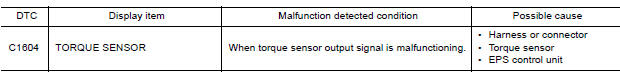
DTC Logic
DTC DETECTION LOGIC
DTC CONFIRMATION PROCEDURE
1.PRECONDITIONING
If "DTC CONFIRMATION PROCEDURE" has been previously conducted, always turn ignition switch OFF and wait at least 10 seconds before conducting the next test.
>> GO TO 2.
2.DTC REPRODUCTION PROCEDURE
With CONSULT
- Turn the ignition switch OFF to ON.
- Perform "EPS" self-diagnosis.
Is DTC "C1604" detected?
YES >> Proceed to diagnosis procedure. Refer to STC "Diagnosis Procedure".
NO >> Inspection End.
Diagnosis Procedure
Regarding Wiring Diagram information, refer to STC "Wiring Diagram".
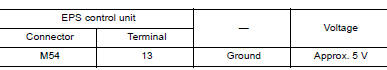
1.CHECK TORQUE SENSOR POWER SUPPLY CIRCUIT
- Turn ignition switch OFF to ON.
CAUTION: Never start the engine.
- Check voltage between EPS control unit harness connector terminal and
ground.
CAUTION: Steering wheel in neutral position. (There is no steering force.)
Is the inspection result normal?
YES >> GO TO 2.
NO >> Perform the trouble diagnosis for battery power supply circuit. Refer to STC "Diagnosis Procedure".
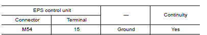
2.CHECK TORQUE SENSOR GROUND CIRCUIT
- Turn ignition switch OFF.
- Check continuity between EPS control unit harness connector terminal and
ground.
CAUTION: Steering wheel in neutral position. (There is no steering force.)
Is the inspection result normal?
YES >> GO TO 3.
NO >> Repair open circuit or short to ground or short to power in harness or connectors.
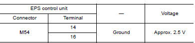
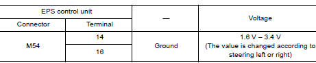
3.CHECK TORQUE SENSOR SIGNAL
- Turn ignition switch OFF to ON.
- Check voltage between EPS control unit harness connector terminal and
ground.
CAUTION: Steering wheel in neutral position. (There is no steering force.)
- Start the engine.
- Check voltage between EPS control unit harness connector terminal and
ground while turning the steering
wheel.
Is the inspection result normal?
YES >> GO TO 4.
NO >> Torque sensor is malfunctioning. Replace steering column assembly. Refer to ST "Removal and Installation".
4.CHECK CONNECTOR
- Turn ignition switch OFF.
- Disconnect EPS control unit harness connector.
- Check terminal for deformation, disconnection, looseness, and so on. If any malfunction is found, repair or replace terminal.
Is the inspection result normal?
YES >> Replace EPS control unit. Refer to STC "Removal and Installation".
NO >> Repair or replace malfunctioning component.
 C1601 Battery power supply
Other materials:
Thermostat
Exploded View
1. Radiator hose (lower) 2. Water inlet 3. Rubber ring
4. Thermostat A. To radiator
Removal and Installation
WARNING:
Do not remove the radiator cap when the engine is hot. Serious burns
could occur from highpressure
engine coolant escaping from the radiator. Wrap a thick cl ...
Line pressure control
LINE PRESSURE CONTROL : System Description
SYSTEM DIAGRAM
DESCRIPTION
Highly accurate line pressure control (secondary pressure control) reduces
friction for improvement of fuel
economy.
Normal Oil Pressure Control
Appropriate line pressure and secondary pressure suitable for driving
c ...
Categories
- Manuals Home
- Nissan Versa Owners Manual
- Nissan Versa Service Manual
- Video Guides
- Questions & Answers
- External Resources
- Latest Updates
- Most Popular
- Sitemap
- Search the site
- Privacy Policy
- Contact Us

0.0064