
Nissan Versa (N17): B1129 - B1132 Side airbag module RH
Description
DTC B1129 - B1132 FRONT RH SIDE AIR BAG MODULE
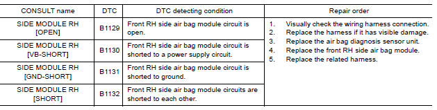
The front RH side air bag module is wired to the air bag diagnosis sensor unit. The air bag diagnosis sensor unit will monitor for opens and shorts in detected lines to the front RH side air bag module.
PART LOCATION
Refer to SRC "Component Parts Location".
DTC Logic
DTC DETECTION LOGIC
With CONSULT
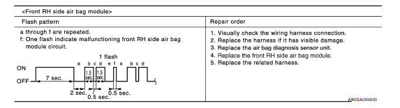
Without CONSULT
DTC CONFIRMATION PROCEDURE (With CONSULT)
1.CHECK SELF-DIAG RESULT
- Turn ignition switch ON.
- Check for DTC using CONSULT.
Is the DTC detected?
YES (Current DTC)>>Refer to SRC "Diagnosis Procedure".
YES (Past DTC)>>GO TO 2.
NO >> Inspection End.
2.ERASE SELF-DIAG RESULT
Erase the DTC using CONSULT.
Can the DTC be erased?
YES >> Inspection End.
NO >> Refer to SRC "Diagnosis Procedure".
DTC CONFIRMATION PROCEDURE (Without CONSULT)
1.CHECK SELF-DIAG RESULT
- Turn ignition switch ON.
- Check the air bag warning lamp status. Refer to SRC "Trouble Diagnosis without CONSULT".
NOTE: SRS will not enter diagnosis mode if no malfunction is detected in user mode.
Is the DTC detected?
YES >> Refer to SRC "Diagnosis Procedure".
NO >> Inspection End.
Diagnosis Procedure
1.HARNESS CONNECTOR
Visually inspect all applicable harness connectors for the following:
- Visible damage to connector or terminal
- Loose terminal
- Poor connection
NOTE: All harness connectors should be inspected from the air bag diagnosis unit to the end component (including any in-line connectors).
Is the inspection result normal?
YES >> GO TO 2
NO >> Perform one of the following repairs:
- Visible damage: Replace the harness.
- Loose terminal: Secure the terminal.
- Poor connection: Secure the connection.
2.CONFIRM DTC
- Reconnect all harness connectors.
- Turn ignition switch ON.
- Check for DTC using CONSULT.
Is DTC still current?
YES >> GO TO 3
NO >> Refer to GI "Intermittent Incident".
3.WIRING HARNESS
Check the wiring harness for visible damage NOTE.
NOTE: The entire wiring harness should be inspected from the air bag diagnosis sensor unit to the end component (including any in-line connectors).
Is the inspection result normal?
YES >> GO TO 4
NO >> Replace the harness.
4.CONFIRM DTC
- Reconnect all harness connectors.
- Turn ignition switch ON.
- Check for DTC using CONSULT.
Is DTC still current?
YES >> GO TO 5
NO >> Refer to GI "Intermittent Incident".
5.AIR BAG DIAGNOSIS SENSOR UNIT
- Replace the air bag diagnosis sensor unit. Refer to SR "Removal and Installation".
- Turn ignition switch ON.
- Check for DTC using CONSULT.
Is DTC still current?
YES >> GO TO 6.
NO >> Clear DTC. Inspection End.
6.SIDE AIR BAG MODULE RH
- Replace the side air bag module RH. Refer to SR "Removal and Installation".
- Turn ignition switch ON.
- Check for DTC using CONSULT.
Is DTC still current?
YES >> GO TO 7.
NO >> Clear DTC. Inspection End.
7.RELATED HARNESS
Replace the related harness.
>> END
 B1134 - B1137 Side airbag module LH
Description DTC B1134 - B1137 FRONT LH SIDE AIR BAG MODULE The front LH side air bag module is wired to the air bag diagnosis sensor unit. The air bag diagnosis sensor unit will monitor for opens ...
B1150 - B1153 Side curtain air bag
module LH
Description DTC B1150 - B1153 LH SIDE CURTAIN AIR BAG MODULE The LH side curtain air bag module is wired to the air bag diagnosis sensor unit. The air bag diagnosis sensor unit will monitor for ...
Other materials:
Air bags, seat belts and child restraints
1. Supplemental air bag modules
2. Roof-mounted curtain side-impact and
rollover supplemental air bag
3. Front seat-mounted side-impact
supplemental air bag
4. Front seat belt with pretensioner(s) and
shoulder height adjuster
5. Head restraints/headrests
6. Rear seat belts
7. LATCH (Low ...
P0507 ISC system
Description
The ECM controls the engine idle speed to a specified level through the fine
adjustment of the air, which is let
into the intake manifold, by operating the electric throttle control actuator.
The operating of the throttle valve is
varied to allow for optimum control of the engine ...
Categories
- Manuals Home
- Nissan Versa Owners Manual
- Nissan Versa Service Manual
- Video Guides
- Questions & Answers
- External Resources
- Latest Updates
- Most Popular
- Sitemap
- Search the site
- Privacy Policy
- Contact Us

0.0092