Nissan Versa (N17): B2556 Push-button ignition switch
DTC Logic
DTC DETECTION LOGIC 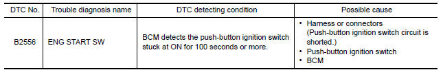
DTC CONFIRMATION PROCEDURE
1.PERFORM DTC CONFIRMATION PROCEDURE
1. Press push-button ignition switch under the following condition.
- Brake pedal: Not depressed
2. Release push-button ignition switch and wait 100 seconds or more.
3. Check DTC in Self Diagnostic Result mode of BCM using CONSULT.
Is DTC detected?
YES >> Go to SEC "Diagnosis Procedure".
NO >> Inspection End.
Diagnosis Procedure
Regarding Wiring Diagram information, refer to SEC "Wiring Diagram".
1.CHECK PUSH-BUTTON IGNITION SWITCH INPUT SIGNAL
1. Turn ignition switch OFF.
2. Disconnect push-button ignition switch connector.
3. Check voltage between push-button ignition switch harness connector and
ground. 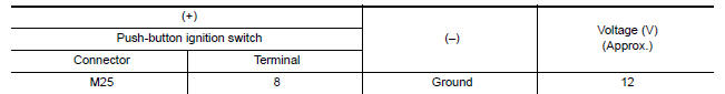
Is the inspection result normal?
YES >> GO TO 4.
NO >> GO TO 2.
2.CHECK PUSH-BUTTON IGNITION SWITCH CIRCUIT
1. Disconnect BCM connector and IPDM E/R connector.
2. Check continuity between push-button ignition switch harness connector and
BCM harness connector.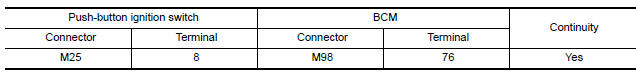
3. Check continuity between push-button ignition switch harness connector and
ground.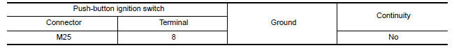
Is the inspection result normal?
YES >> GO TO 3.
NO >> Repair or replace harness.
3.REPLACE BCM
1. Replace BCM. Refer to BCS "Removal and Installation".
2. Perform initialization of BCM and registration of all Intelligent Keys using CONSULT.
>> Inspection End.
4.CHECK PUSH-BUTTON IGNITION SWITCH GROUND CIRCUIT
Check continuity between push-button ignition switch harness connector and
ground. 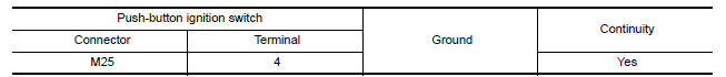
Is the inspection result normal?
YES >> GO TO 5.
NO >> Repair or replace harness.
5.CHECK PUSH-BUTTON IGNITION SWITCH
Refer to SEC "Component Inspection".
Is the inspection result normal?
YES >> GO TO 6.
NO >> Replace push-button ignition switch. Refer to SEC "Removal and Installation".
6.CHECK INTERMITTENT INCIDENT
Refer to GI "Intermittent Incident".
>> Inspection End.
Component Inspection
1.CHECK PUSH-BUTTON IGNITION SWITCH
1. Turn ignition switch OFF.
2. Disconnect push-button ignition switch connector.
3. Check continuity between push-button ignition switch terminals. 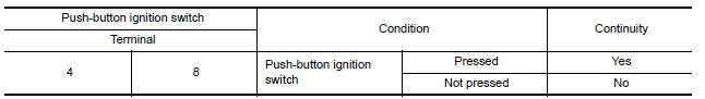
Is the inspection reult normal?
YES >> Inspection End.
NO >> Replace push-button ignition switch. Refer to SEC "Removal and Installation".
 B2555 Stop lamp
Other materials:
Remote keyless entry system (if so equipped)
WARNING
Radio waves could adversely affect
electric medical equipment. Those who
use a pacemaker should contact the
electric medical equipment manufacturer
for the possible influences before
use.
The remote keyless entry key fob transmits
radio waves when the buttons are
pressed. ...
Camshaft valve clearance
Inspection and Adjustment
INSPECTION
Perform inspection as follows after removal, replacement or installation of
camshaft or valverelated parts, or if
there are unusual engine conditions regarding valve clearance.
Remove rocker cover.
Measure the valve clearance with the following proced ...
Categories
- Manuals Home
- Nissan Versa Owners Manual
- Nissan Versa Service Manual
- Video Guides
- Questions & Answers
- External Resources
- Latest Updates
- Most Popular
- Sitemap
- Search the site
- Privacy Policy
- Contact Us

0.0061