Nissan Versa (N17): B2604 Shift position
DTC Logic
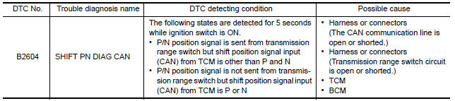
DTC DETECTION LOGIC
NOTE:
- If DTC B2604 is displayed with DTC U1000, first perform the trouble diagnosis for DTC U1000. Refer to BCS "DTC Logic".
- If DTC B2604 is displayed with DTC U1010, first perform the trouble
diagnosis for DTC U1010. Refer to
BCS "DTC Logic".
DTC CONFIRMATION PROCEDURE
1.PERFORM DTC CONFIRMATION PROCEDURE
1. Shift the selector lever to the P position.
2. Turn ignition switch ON and wait 5 seconds or more.
3. Shift the selector lever to the N position and wait 5 seconds or more.
4. Shift the selector lever to any position other than P and N, and wait 5 seconds or more.
5. Check DTC in Self Diagnostic Result mode of BCM using CONSULT.
Is DTC detected?
YES >> Go to SEC "Diagnosis Procedure".
NO >> Inspection End.
Diagnosis Procedure
Regarding Wiring Diagram information, refer to SEC "Wiring Diagram".
1.CHECK DTC OF TCM
Check DTC in Self Diagnostic Result mode of TCM using CONSULT.
Is DTC detected?
YES >> Perform the trouble diagnosis related to the detected DTC. Refer to TM "DTC Index".
NO >> GO TO 2.
2.CHECK FUSE
1. Turn power switch OFF.
2. Check that the following fuse in IPDM E/R is not blown. 
Is the inspection result normal?
YES >> GO TO 3.
NO >> Replace the blown fuse after repairing the cause of blowing.
3.CHECK TRANSMISSION RANGE SWITCH POWER SUPPLY
1. Disconnect transmission range switch connector.
2. Turn ignition switch ON.
3. Check voltage between transmission range switch harness connector and
ground. 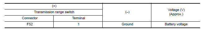
Is the inspection result normal?
YES >> GO TO 5.
NO >> GO TO 4.
4.CHECK TRANSMISSION RANGE SWITCH POWER SUPPLY CIRCUIT
1. Turn ignition switch OFF.
2. Disconnect IPDM E/R connector.
3. Check continuity between transmission range switch harness connector and
IPDM E/R harness connector.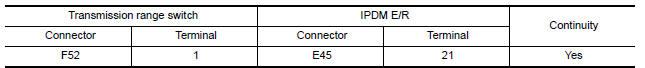
Is the inspection result normal?
YES >> Replace IPDM E/R. Refer to PCS "Removal and Installation".
NO >> Repair or replace harness.
5.CHECK BCM INPUT SIGNAL
1. Turn ignition switch OFF.
2. Reconnect transmission range switch connector.
3. Turn ignition switch ON.
4. Check voltage between BCM harness connector and ground. 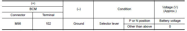
Is the inspection result normal?
YES >> GO TO 9.
NO >> GO TO 6.
6.CHECK BCM INPUT SIGNAL CIRCUIT
1. Turn ignition switch OFF.
2. Disconnect transmission range switch connector.
3. Disconnect BCM connector.
4. Check continuity between transmission range switch harness connector and
BCM harness connector.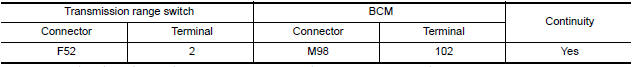
5. Check continuity between transmission range switch harness connector and
ground.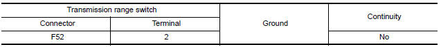
Is the inspection result normal?
YES >> GO TO 7.
NO >> Repair or replace harness.
7.CHECK TRANSMISSION RANGE SWITCH
Refer to SEC "Component Inspection".
Is the inspection result normal?
YES >> GO TO 8.
NO >> Replace transmission range switch.
8.CHECK INTERMITTENT INCIDENT
Refer to GI "Intermittent Incident".
>> Inspection End.
9.REPLACE BCM
1. Replace BCM. Refer to BCS "Removal and Installation".
2. Perform initialization of BCM and registration of all Intelligent Keys using CONSULT.
>> Inspection End.
Component Inspection
1.CHECK TRANSMISSION RANGE SWITCH
1. Turn ignition switch OFF.
2. Disconnect transmission range switch connector.
3. Check continuity between transmission range switch terminals. 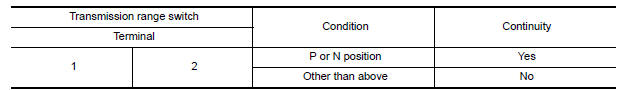
Is the inspection result normal?
YES >> Inspection End.
NO >> Replace transmission range switch.
 B2603 Shift position
Other materials:
Precautions when starting and driving
WARNING
Do not leave children or adults who
would normally require the assistance
of others alone in your vehicle. Pets
should also not be left alone. They
could accidentally injure themselves or
others through inadvertent operation of
the vehicle. Also, on hot, sunny days,
tempera ...
Push-button ignition switch (if so equipped)
WARNING
Do not operate the push-button ignition
switch while driving the vehicle except in
an emergency. (The engine will stop when
the ignition switch is pushed 3 consecutive
times in quick succession or the ignition
switch is pushed and held for more
than 2 seconds.) If the engine stops ...
Categories
- Manuals Home
- Nissan Versa Owners Manual
- Nissan Versa Service Manual
- Video Guides
- Questions & Answers
- External Resources
- Latest Updates
- Most Popular
- Sitemap
- Search the site
- Privacy Policy
- Contact Us

0.0059