Nissan Versa (N17): B2614 ACC Relay circuit
DTC Logic
DTC DETECTION LOGIC
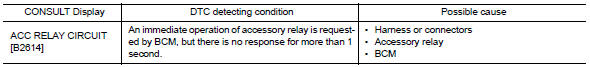
DTC CONFIRMATION PROCEDURE
1.PERFORM DTC CONFIRMATION PROCEDURE
1. Turn ignition switch to ACC, and wait for 1 second or more.
2. Check "Self-diagnosis result" of BCM with CONSULT.
Is DTC detected?
YES >> Go to PCS "Diagnosis Procedure".
NO >> Inspection End.
Diagnosis Procedure
Regarding Wiring Diagram information, refer to PCS "Wiring Diagram".
1.CHECK ACCESSORY RELAY CONTROL SIGNAL
Check voltage between BCM harness connector and ground.
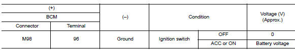
Is the inspection result normal?
YES >> Replace BCM. Refer to BCS "Removal and Installation".
NO >> GO TO 2.
2.CHECK ACCESSORY RELAY CONTROL SIGNAL CIRCUIT
1. Turn ignition switch OFF.
2. Disconnect BCM connector and accessory relay.
3. Check continuity between BCM harness connector and accessory relay harness
connector.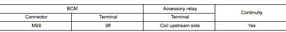
4. Check continuity between BCM harness connector and ground.
Is the inspection result normal?
YES >> GO TO 3.
NO >> Repair or replace harness.
3.CHECK ACCESSORY RELAY
Refer to PCS "Component Inspection".
Is the inspection result normal?
YES >> Replace BCM. Refer to BCS "Removal and Installation".
NO >> Replace accessory relay.
Component Inspection
1.CHECK ACCESSORY RELAY
1. Turn ignition switch OFF.
2. Remove accessory relay.
3. Check the continuity between accessory relay terminals.
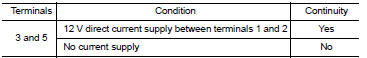
Is the inspection result normal?
YES >> Inspection End.
NO >> Replace accessory relay
 U1000 CAN Comm circuit
Description Refer to LAN "CAN COMMUNICATION SYSTEM : System Description". DTC Logic DTC DETECTION LOGIC NOTE: U1000 can be set if a module harness was disconnected and reconnected, ...

Other materials:
Trunk lid
WARNING
Do not drive with the trunk lid open. This
could allow dangerous exhaust gases
to be drawn into the vehicle. For additional
information, refer to "Exhaust
gas (carbon monoxide)" in the "Starting
and driving" section of this manual.
Closely supervise children when they
are a ...
Recommended fluids/lubricants and capacities
The following are approximate capacities. The actual refill capacities may
be a little different. When refilling, follow the procedure
described in the "Do-it-yourself" section to determine the proper refill
capacity.
...
Categories
- Manuals Home
- Nissan Versa Owners Manual
- Nissan Versa Service Manual
- Video Guides
- Questions & Answers
- External Resources
- Latest Updates
- Most Popular
- Sitemap
- Search the site
- Privacy Policy
- Contact Us

0.0057