Nissan Versa (N17): B2615 Blower relay circuit
DTC Logic
DTC DETECTION LOGIC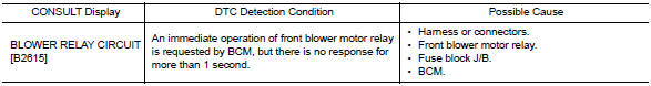
DTC CONFIRMATION PROCEDURE
1.PERFORM DTC CONFIRMATION PROCEDURE
1. Turn ignition switch ON, and wait for 1 second or more.
2. Check "Self-diagnosis result" with CONSULT.
Is DTC detected?
YES >> Go to PCS "Diagnosis Procedure".
NO >> Inspection End.
Diagnosis Procedure
Regarding Wiring Diagram information, refer to PCS "Wiring Diagram".
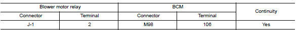
1. CHECK BLOWER MOTOR RELAY POWER SUPPLY CIRCUIT
1. Turn ignition switch OFF.
2. Disconnect blower motor relay.
3. Disconnect BCM connector M19.
4. Check continuity between blower motor relay connector J-1 terminal 2 and
BCM connector M98 terminal
106.
5. Check continuity between Blower motor relay connector J-1 terminal 2 and
ground.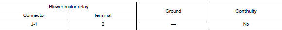
Is the inspection result normal?
YES >> GO TO 2.
NO >> Repair or replace harness or connectors.
2. CHECK BLOWER MOTOR RELAY GROUND CIRCUIT
1. Check continuity between Blower motor relay connector J-1 terminal 1 and
ground.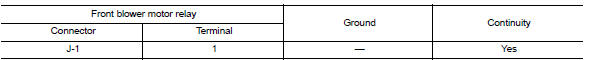
Is the inspection result normal?
YES >> GO TO 3.
NO >> Repair or replace harness or connectors.
3. CHECK BLOWER MOTOR RELAY
Perform the relay component inspection. Refer to HAC "Component Inspection (Blower Relay)".
Is the inspection result normal?
YES >> GO TO 4.
NO >> Replace blower motor relay.
4. CHECK BLOWER MOTOR RELAY POWER SUPPLY (BCM)
Check voltage between BCM connector M98 terminal 106 and ground.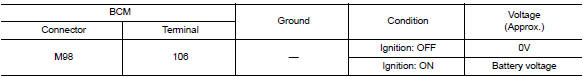
Is the inspection result normal?
YES >> Refer to GI "Intermittent Incident".
NO >> Replace BCM. Refer to BCS "Removal and Installation".
Component Inspection
1.CHECK BLOWER RELAY
1. Turn blower switch OFF.
2. Remove blower relay.
3. Check the continuity between blower relay terminals.
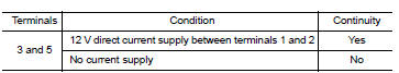
Is the inspection result normal?
YES >> Inspection End.
NO >> Replace blower relay
 B2614 ACC Relay circuit
Other materials:
Idle air volume learning
Description
Idle Air Volume Learning is a function of ECM to learn the idle air volume
that keeps each engine idle speed
within the specific range. It must be performed under any of the following
conditions:
Each time electric throttle control actuator or ECM is replaced.
Idle speed or ...
Precautions
Precaution for Supplemental Restraint System
(SRS) "AIR BAG" and "SEAT BELT PRE-TENSIONER"
The Supplemental Restraint System such as "AIR BAG" and "SEAT BELT PRE-TENSIONER",
used along
with a front seat belt, helps to reduce the risk or severity of injury to the
driver and ...
Categories
- Manuals Home
- Nissan Versa Owners Manual
- Nissan Versa Service Manual
- Video Guides
- Questions & Answers
- External Resources
- Latest Updates
- Most Popular
- Sitemap
- Search the site
- Privacy Policy
- Contact Us

0.0064